Fluid Components International GF03 User Manual
Page 27
Doc. No. 06EN003352 Rev. B
2 3
Model GF03 Flow Meter
FLUID COMPONENTS INTERNATIONAL LLC http://www.fluidcomponents.com
Setting Analog Outputs
The flowmeter has two, independent analog signal outputs. The outputs can be set to represent
flow rate or temperature. The flowmeter signal outputs have been configured according to the
application information supplied to the factory at the time of order. However, the outputs can
be re-scaled anywhere within the calibrated flow range. The ouputs can be independently set
to one of the four ranges: 4 to 20 mA, 0 to 5 V, 0 to 10 V, or 1 to 5 V. A typical configuration
is presented in Table 7.
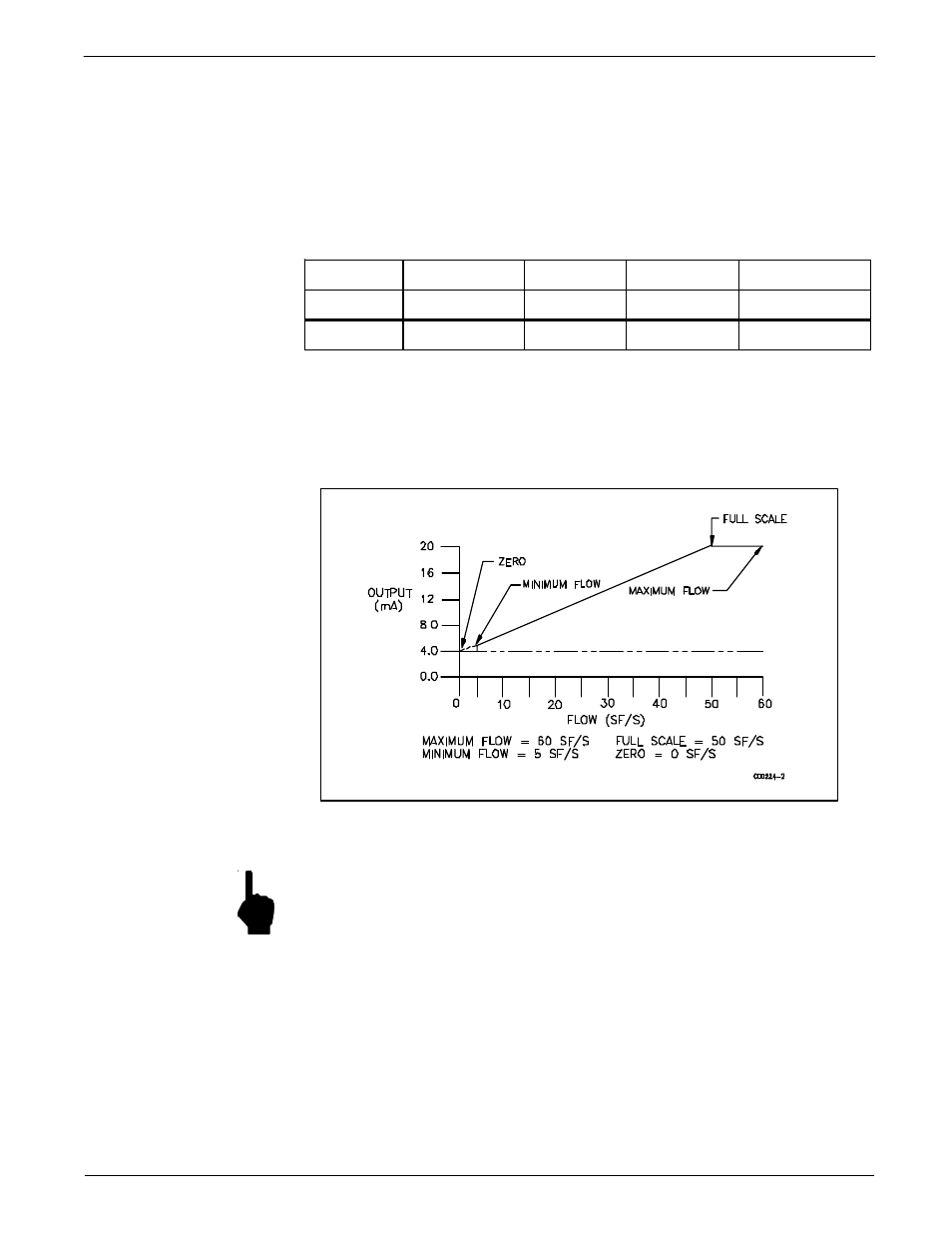
The signal range varies linearly with change in flow rate as shown in Figure 14. Minimum
Port No.
Mode
Type
Zero
Full-Scale (F.S.)
1
4 to 20mA
Flow
0 SF/S
150 SF/S
2
4 to 20mA
Temp
-50°F
150°F
Table 7 - Typical Signal Output Configuration
signal output can be set to indicate a flow of zero. This is often referred to as a zero-based
signal output. A minimum signal that represents a value greater than zero is referred to as non-
zero based.
Figure 14 - Signal Output versus Flow Rate
NOTE:
The flowmeter inherently has a minimum, non-zero flow rate that it is able to
detect. Therefore, setting the minimum signal output (referred to as Zero in Menu
2.1.1) to zero will create a step in the output. This step corresponds to the flow
where the flowmeter begins accurate measurement. Turndown ratios ( turndown
is defined as the maximum flow rate divided by the minimum flow rate) smaller
than 10:1 will have a large step change thus reducing the usable signal range.