Fluid Components International GF03 User Manual
Page 33
Doc. No. 06EN003352 Rev. B
2 9
Model GF03 Flow Meter
FLUID COMPONENTS INTERNATIONAL LLC http://www.fluidcomponents.com
+20V
1 AUX
+E OUT 2
OUT 2 COM
+I OUT 2
+E OUT 1
OUT 1 COM
+I OUT 1
JP6
C00249-1
The relationship between the measured and the desired flow rates was determined through a
least squares analysis. The coefficients for the above relation are:
F
1
= -7.5672
F
2
= 2.09253
F
3
= -0.037082
F
4
= 0.0003505
w
To enter the correction equation coefficients and to enable it:
1.
From the Main menu press 4. The 4.0 MISCELLANEOUS menu title will appear.
2.
Press 2, the Corrector Setup option.
3.
Press 2, the Enter Corr option, to enter the Correction Equation coefficients
4.
Enter the user password (if it is enabled). Press 1 to enter the coefficient F1. Press
2 for F2 and so on to F4. Press 5 to verify the entries.
5.
Press 6 to exit.
6.
Press 1 to enable to Corrector. (To disable the Corrector press 1 again.)
The flowmeter has one analog signal input port that can be used to directly manipulate the flow
rate output. This signal input port is called the auxiliary input. The signal measured by the
flowmeter allows for the correction of errors that may be caused by changes such as process
composition. The factory has determined from the application data supplied at the time of
order whether the flowmeter would benefit from using the auxiliary input. If the auxiliary
input is not used in the flowmeter the following section can be skipped. If the auxiliary input
is used, all the internal settings necessary have been entered into the flowmeter. The following
is a description of the internal and external workings of the auxiliary input.
w
To determine if the flowmeter is set to use the auxiliary input:
1.
From the Main menu press 2. The 2.0 PORT SETUP menu title will appear.
2.
Press 4, the Aux Input option.
3.
Press 2, the Enter Aux option. Enter the user password (if it is enabled).
4.
Press 5, the Verify option. The variables AUX 1, 2 and 3 will appear.
5.
Press ENTR and DISABLED or ENABLED will be on the third line. If ENABLED
is displayed then the flowmeter has been configured to use the auxiliary input.
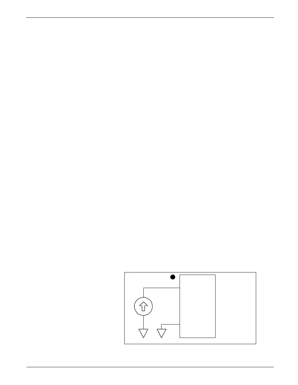
The auxiliary input is accessed at terminal JP6 located on the lower circuit board. Figure 22
illustrates the auxiliary input connected to a current source. If OUT 1 COM is not easily
accessible then use JP6 OUT 2 COM, JP7 GND, JP1 DC GND OR JP3 GND. They are
electrically the same signal ground point. The range of this source is most likely 4-20mA.
Figure 22 - Auxiliary Input Wiring Diagram
The Auxiliary Input