General information – Fluid Components International GF03 User Manual
Page 5
Doc. No. 06EN003352 Rev. B
1
Model GF03 Flow Meter
FLUID COMPONENTS INTERNATIONAL LLC http://www.fluidcomponents.com
1. General Information
This document describes the procedures required to install, operate, maintain, and troubleshoot
the Model GF03 Flowmeter. There are a wide range of possible configurations and information
related to the optional features. The flowmeter is composed of a remote thermal dispersion
sensing transducer (flow element) connected to a microprocessor-based electronics control
and display package (flow transmitter). The flow element is attached to the flow transmitter
thru a cable of up to 1000 feet or 300 meters (remote instrument).
The instrument is designed to operate in gaseous flow metering environments. The flowmeter
is factory calibrated to handle a range of flows.
The primary flow element consists of two thermowells of the same size, shape and mass. One
thermowell contains a platinum RTD and a heater element. The other contains one RTD. The
RTD located with the heater element is called the active RTD. The other RTD is referred to
as the reference RTD. Since the active RTD is embeded in the heater, the temperature of the
active thermowell is always above the temperature of the process media. The temperature at
the reference RTD is the temperature of the process media. When the process media is flowing
past the active RTD a quantity of heat is carried off into the flow stream. The amount of heat
taken from the active RTD is a function of the process media mass flow rate. A
∆
T
(temperature) exists between the two thermowells and a proportional
∆
R (ohms resistance)
exists between the active and the reference RTDs. The
∆
R is measured by the flow transmitter.
The relationship of
∆
R to the calibrated flow rate is calculated by the flow transmitter and is
converted into both analog and digital outputs.
The Gas Compensation element provides a
∆
R value similar to the primary flow element. This
value is a no-flow
∆
R based on the thermo physical properties of the gas mixture minus any
flow component. This value is used to correct gas composition changes in the Transmitter
microprocessor.
Description
Theory of Operation
Sensing Element
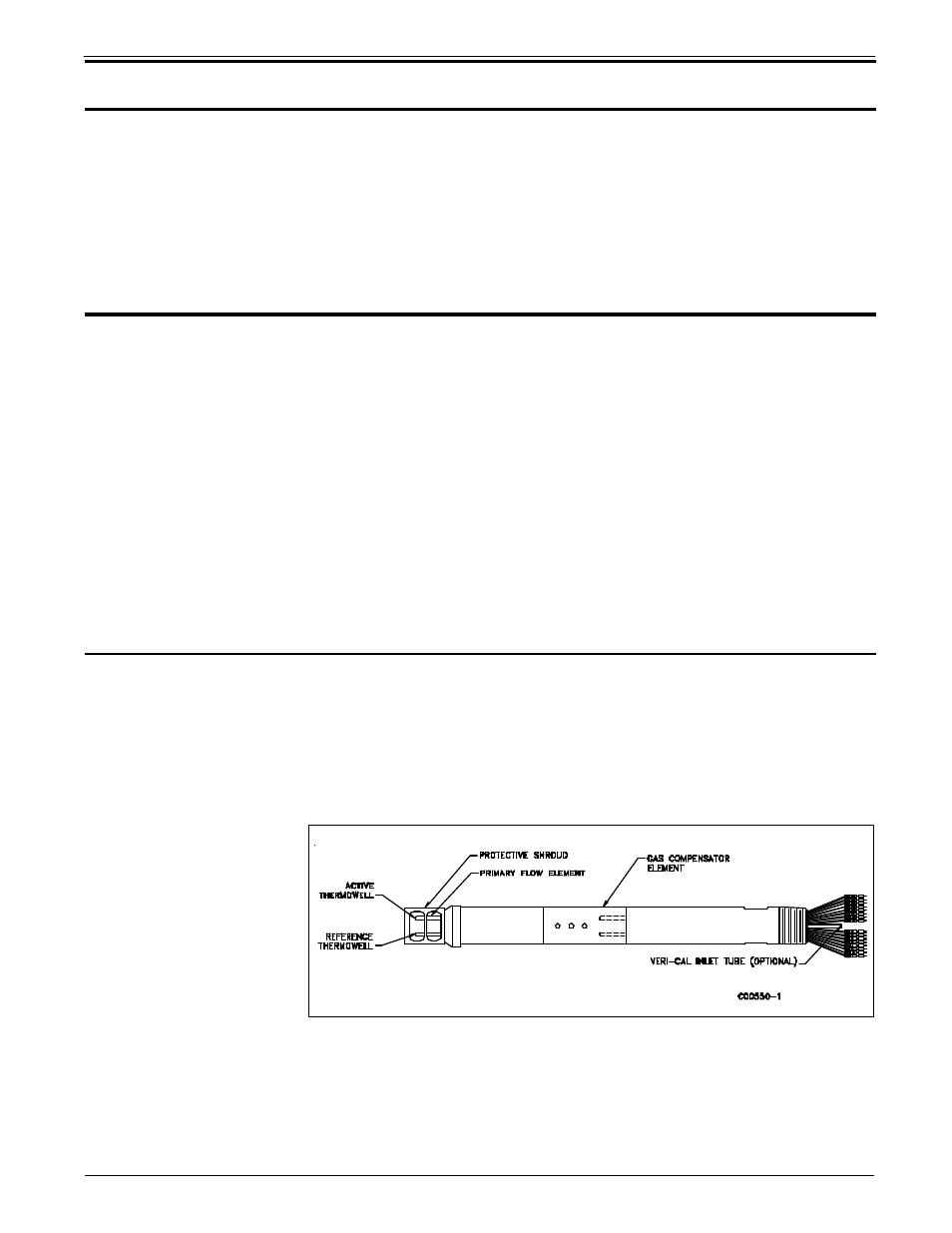
The standard sensing element is an all welded 316L stainless steel insertion probe. The
element consists of the primary flow element located on the end of the probe and the
compensator element located in the insertion pipe. The optional Veri-Cal inlet tube runs
the length of the insertion pipe exiting into the base of the primary flow element. This tube
allows the Veri-Cal system to distribute a repeatable flow rate on the primary flow element
for calibration verification purposes.
Figure 1 - Flow Element