Fluid Components International GF03 User Manual
Page 11
Doc. No. 06EN003352 Rev. B
7
Model GF03 Flow Meter
FLUID COMPONENTS INTERNATIONAL LLC http://www.fluidcomponents.com
Flange Mounting
w
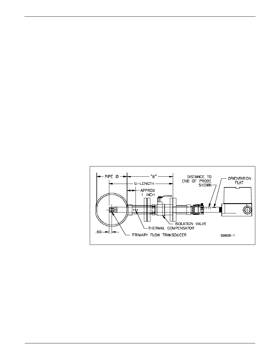
Attach the process mating flange with care. The correct orientation of the flow element
must be maintained to ensure the calibrated accuracy.
w
Verify that the process media flow is in the same direction as the arrow on the FLAT.
w
Apply the appropriate gasket and/or sealant to flange mount as required.
w
Mate flow element flange to process mount keeping flat oriented properly.
w
Attach with bolt, two flat washers, lock washer and nut for each bolt hole, apply lubricant/
sealant to male threads and torque. Refer to ANISI B16.5 specifications.
General Mounting
w
Tighten packing nut until internal packing is tight enough so that the friction fit on the
shaft is adequate to prevent leakage but not prevent the shaft from sliding. Position the
flat horizontal with arrow in direction of process flow.
w
Proceed to insert the flow element into process media line. For the medium pressure
packing gland use the adjusting nuts on the all-thread to pull the flow element into proper
predetermined depth position.
w
Tighten the opposing lock nuts on the all-threads. Tighten the packing nut another 1/2
to 1 turn until tight (approximately 65 to 85 ft-lbs torque).
w
Rotate split ring locking collar to line up with connecting strap welded to packing nut.
Tighten the two 1/4-28 hex socket cap screws on the split ring locking collar. Open valve
- check for process media leakage.
w
Reverse these steps for removal.
Figure 4 - Flange Mount