In-depth troubleshooting the flow element – Fluid Components International GF03 User Manual
Page 46
FLUID COMPONENTS INTERNATIONAL LLC http://www.fluidcomponents.com
Model GF03 Flow Meter
4 2
Doc. No. 06EN003352 Rev. B
Check Serial Numbers
Verify that the serial number of the flow element and the flow transmitter are the same. The
flow element and the flow transmitter are a matched set and cannot be operated independently
of each other. The only exception is when the flow transmitter has been specifically
configured to be a replacement.
Check the Resistance of the Flow Element
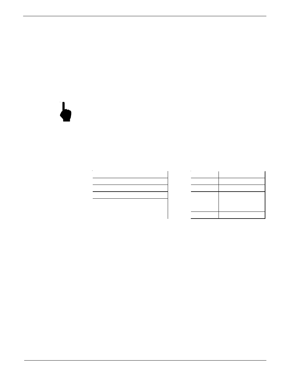
Use Tables 9 and 10 to determine if the flow element is wired incorrectly or has failed. Turn
off the input power to the transmitter. Unplug the flow element at JP3 located on the lower
board and measure resistances described below by touching the DMM test leads to the JP3
terminal screws. (Remember to reconnect JP3 back to the flow transmitter when finished.)
Repeat resistance check on TS2.
NOTE:
If the system does not allow the disconnection of the flowmeter power, or
unplugging the flow element, then proceed to the section, "In-Depth
Troubleshooting - The Flow Transmitter".
All resistances in Tables 9 and 10 are based on a temperature of 32°F (0 °C). Resistances
acrosst the ACT and the REF RTD’s are approximately 1080 ohms* at 70 °F ( 21 °C ). The
resistances will continue to increase for higher temperatures at the flow element. Check
resistance from each pin in the local/remote enclosure to case ground. There should be an
infinite resistance.
In-Depth
Troubleshooting
The Flow Element
Pin Number
Approximate Resistance
1 to 2
0 Ohms
2 to 3
1000 Ohms
2 to 4
1000 Ohms
2 to 5
1000 Ohms
2 to 6
1000 Ohms
2 to 7
115 Ohms
Table 9 - Resistance at JP3
Terminal Plug
Primary Flow Element
Table 10 - Resistance at TS2
Compensator Elemenet
Pin Number
Approximate Resistance
1 to 2
0 Ohms
2 to 3
1000 Ohms
2 to 4
1000 Ohms
3 to 4
2000 Ohms
4 to 6 , 3 to 5
0 Ohms
7 to 8
110 – 118 Ohms
If the measured resistances do not correspond to Tables 9 and 10 then the flow element is
functioning properly. The problem lies else where. Skip the rest of this section and proceed
with the section, In-Depth Troubleshooting - The flow transmitter. If the measured values do
not correspond to Table 5-2 then a problem exists in the flow element. For remote instruments,
with a cable between the flow element and the flow transmitter, the cable could be shorted or
open. To isolate a problem with the cable, check the flow element resistances at the terminal
block located within the flow element (local) enclosure. Disconnect the wires from the
terminal block and measure resistances described below by touching the DMM test leads to
the terminal block screws. The measured resistances should correspond approximately to the
values in Table 5-3.
If the measured resistances correspond to Table 5-3 then the cable or wiring is defective.
Contact customer service for details on how to obtain another cable or flow element.