Fluid Components International GF03 User Manual
Page 30
FLUID COMPONENTS INTERNATIONAL LLC http://www.fluidcomponents.com
Model GF03 Flow Meter
2 6
Doc. No. 06EN003352 Rev. B
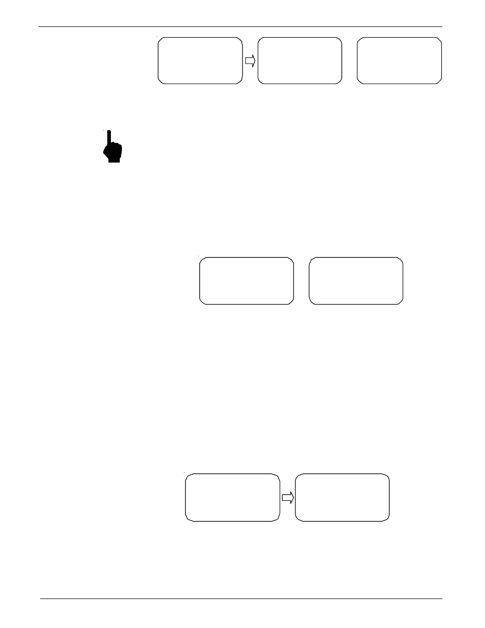
FLOW
Flow Factor: 5.30
0.530 to 1591
SCFM
FLOW
Standard Density:
0.07497 LBM/FT3
Window 1
Window 2
AREA/PIPE I.D.
Area = 12.73 sq in
I.D.=4.026 in
HIT anykey to EXIT
Window 3
C00243-1
NOTE
:
The flowmeter does not measure standard density. This number is entered through
menu level 7.3.5. The standard density displayed in menu 5.2 must be equivalent
to the standard density of the process media. The factory has entered the process
standard density supplied at the time of order. The standard density factor is only
used when calculation mass flow units.
w
To view the temperature and totalizer units of measure:
1.
From the Main menu press 5. The 5.0 VERIFY menu title will appear.
2.
Press 5 to view the current units for temperature. Press 3 to view the current units for
the total flow. (If the totalizer is disabled the display will only show No Totalizer.)
The information will be displayed to the screen as shown in Figure 17.
TEMPERATURE:
Temp units: °F
Tcal Add = 0.000
Tcal Mult = 1.000
Totalizer Units:
SCF
HIT any key to EXIT
Window 1
Window 2
C00244-1
Line 2 of screen 1 shows the current units for temperature. Lines 3 and 4 display the offset
and multiplier to the measured temperature. See Advanced Features for a detailed explanation.
Screen 2 shows the total flow units.
w
To view the analog output parameters:
1.
From the Main menu press 5. The 5.0 VERIFY menu title will appear.
2.
Press 6, the Ports option. The two screens in Figure 18 are identical except for the
port number. Line 2 is the current signal output mode. Line 3 shows the full scale
flow rate or temperature value and the appropriate units. Line 4 is the zero value.
Press any key for screen 2.
Figure 17 - Temperature, Totalizer Verification Display
Figure 16 - Flow and Area Verification
PORT 1
Mode: 4-20 mA
F.S. : 1591 SCFM
ZERO: 0.00 SCFM
PORT 2
Mode: 4-20 mA
F.S. : 150 °F
ZERO: -50 °F
Window 1
Window 2
C00245-1
Figure 18 - Analog Output Verification