Fluid Components International GF03 User Manual
Page 20
FLUID COMPONENTS INTERNATIONAL LLC http://www.fluidcomponents.com
Model GF03 Flow Meter
1 6
Doc. No. 06EN003352 Rev. B
Menu Organization
The menu structure is divided into 8 major groups. The first menu option places the flow
transmitter's display into the Normal Display mode. When the system is in this mode, flow
and temperature measurements are displayed. While in the Normal Display mode, pressing
any key will cause the main menu to display. Figure 13 shows the entire menu structure.
Menu selections two through eight allow the configuration of the flowmeter to be checked
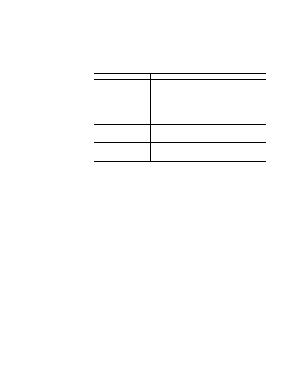
and manipulated. Table 4 summarizes the functions contained in each menu group.
Group Name
Function
2.0 Port Setup
Sets analog outputs, set relay switch point and
configure the auxiliary input.
3.0 Display Setup
Sets the units of measure for the displayed flow
rate, temperature and total flow. Sets the sample
rate.
4.0 Miscellaneous
Sets the current calibration group. Configures
the Corrector. Sets the user password.
5.0 Verify
Displays system variables to the screen.
6.0 Diagnostics
Factory use only.
7.0 Calibration
Displays Delta R in ohms.
8.0 Normalize Board
Factory use only.
The Port Setup, Display Setup and Miscellaneous groups is where most activity is concentrated.
The Verify, Diagnostics, Calibration and Normalize Board groups are used primarily for
diagnostics and factory calibration.
Normal Operation
The flowmeter upon power up defaults to this mode. During normal operation the flow rate
and the temperature is displayed. The total flow is displayed if it is enabled and few system
configuration parameters are shown. Figure 9 is the Normal Operation display.
The first and second lines contain the current flow rate and temperature. The total flow is
displayed on the third line only if it is enabled. The last line contains the current Group
number (see the Multiple Groups section in Advanced Features), the relay status, the mode
of operation and the sample rate.
The relays status shows either e (energized) or d (de-energized). The letters correspond to
the first and second relays, respectively. The mode of operation is norm for normal, auto for
Auto-Select or link for Link Groups. (See Advanced Features for explanation of these
modes). The sample rate is slow (s), medium (m) or fast (f).
Table 4 - Menu Functions