Fluid Components International GF03 User Manual
Page 13
Doc. No. 06EN003352 Rev. B
9
Model GF03 Flow Meter
FLUID COMPONENTS INTERNATIONAL LLC http://www.fluidcomponents.com
Input Power
The flow transmitter is powered by 115 VAC, 230 VAC or 24VDC (only one power source
is needed). If 115 VAC is used, wire it directly to JP8 and position switch S1 to be in the 115V
position. If 230 VAC is used, position switch S1 to be in the 230V position and then wire the
power directly to JP8. If 24 VDC is used, it is wired directly to JP8 as shown on the wiring
diagram.
The installation of an AC line disconnect switch (and possibly a fuse) between the power
source and the flowmeter is strongly recommended. This facilitates easy power disconnection
during calibration and maintenance procedures as well as an added safety feature.
Remote Transmitter
Route all interconnecting wiring into the remote transmitter enclosure. Ensure wires are
long enough with sufficient service loops to eliminate excessive strain on the terminal
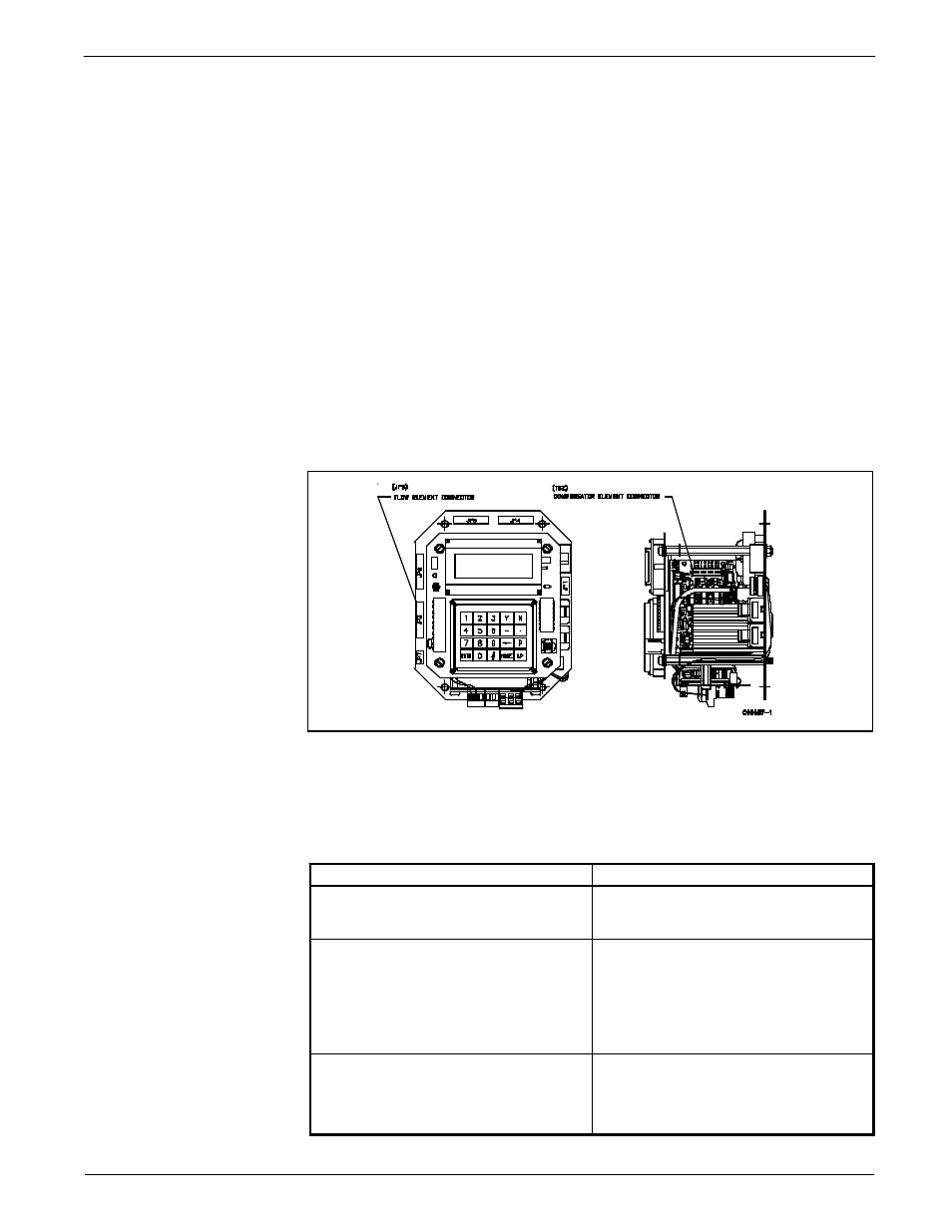
connections. Connect Flow and Analyzer element cables as shown on wiring diagram.
The display orientation varies for different transmitter configurations, but the termination
block for the element connection remains the same. If the Veri-Cal option was ordered,
wire the pressure transducer as shown on the wiring diagram.
Customer Wiring
Jacks JP3 (top circuit board), JP4, JP5, JP6 and JP7 are for customer use and are
described in Table 2.
JACK / NOMENCLATURE
DESCRIPTION
JP3 (top circuit board)
RS-232 (EIA-232) Serial Port
Used in conjunction with equipment compatible
with an RS-232 (EIA-232) serial port. See Chapter
3 for more details.
JP4 Relay Output 1
and
JP5 Relay Output 2
Factory pre-programmable relay contacts. Two
normally closed contacts are available (double pole,
single throw relay) per jack. External relays can be
connected to the +EXT and -EXT pins in each jack.
Recommended relays are 18Vdc, 0.1A. max at 180
or more ohms pull i n current.
JP6 Analog Output
There are two factory pre-programmable signals
which are voltage and/or current. The 1 AUX and
+20V pin is a customer option for the use as a
dynamic correction factor. See Chapter 3 for more
information.
Figure 5 - Electronics Assembly
Table 2 - Customer Wiring