Setting the relays – Fluid Components International GF03 User Manual
Page 28
FLUID COMPONENTS INTERNATIONAL LLC http://www.fluidcomponents.com
Model GF03 Flow Meter
2 4
Doc. No. 06EN003352 Rev. B
w
To re-scale the signal outputs:
1.
From the Main menu press 2. The 2.0 PORT SETUP menu title will appear.
2.
Press 1, the Analog Output option.
3.
Press 1 or 2, corresponding to the analog port to be re-scaled.
4.
After entering the user password (if it is enabled), press 1 to change the analog
output mode. Select the signal mode. (The current selection is shown in
parenthesis to the left of the question mark.)
5.
Press 2 to change the analog output type. Press 1 for an output signal based on
flow. Press 2 for an output signal based on temperature.
6.
Press 3 to change the maximum or Full Scale (F.S.) flow rate. Enter a maximum
flow rate value within the specified range.
7.
Press 4 to change the zero flow rate. Enter a minimum flow rate value within
the specified range. A value of zero is valid.
8.
Press 5 to save and exit to the previous menu level. Press Y when asked to save
permanently.
There are two double pole, double throw relays on the flowmeter. They can be set to
respond to changing flow rates or changing temperatures.
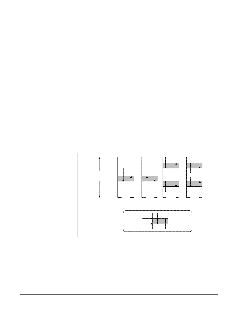
There are four types of switching schemes to choose from. These are referred to as Above,
Below, Outside, and Inside. Each switch point can be set to have hysteresis and a time delay.
Figure 15 illustrates the four switch point schemes with arbitrary hysteresis assigned.
Switching schemes, Above and Below change relay states when the flow or temperature
crosses the switch point value. The outside and inside schemes contain a range wherein the
relay changes states.
Setting the Relays
Above
OFF
ON
Below
OFF
ON
Outside
ON
OFF
Inside
ON
OFF
Switch point
Deactivation
}
Hysterisis
C00225-2
Flow
or
Temperature
Figure 15 - Relay Switch Point Schemes