In-depth troubleshooting the flow transmitter – Fluid Components International GF03 User Manual
Page 47
Doc. No. 06EN003352 Rev. B
4 3
Model GF03 Flow Meter
FLUID COMPONENTS INTERNATIONAL LLC http://www.fluidcomponents.com
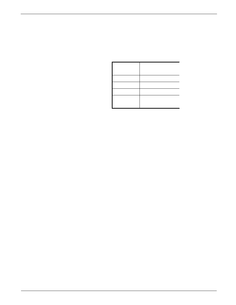
If the measured voltages correspond to Table 12 then the power supplied to and the signals
returning from the flow element are correct. The problem is most likely a corrupted calibration
parameter. Continue troubleshooting at the next section. If the measured values do not
correspond to Table 12 and the flow element was proven to function correctly (see previous
section), then the flow transmitter is defective. If the previous section checks were not
possible and the above values did not correspond, then the problem could be in the flow
element or the flow transmitter. Contact Customer Service for details on how to obtain
replacements.
In-Depth
Troubleshooting
The Flow Transmitter
Pin Number
Approximate Voltage
1 to 2
0
2 to 3
1.1
2 to 4
1.2
2 to 5
1.1
2 to 6
1.2
2 to 7
16.5
Table 12
Voltage Readings in Volts DC at JP3
Check the Voltages Across the RTD Leads
This is done without disconnecting any flow element wires. Voltage measurements can be
made at JP3 located on the lower circuit board. Measure voltages described below by touching
the DMM test leads to the terminal screws. The expected voltages are given in Table 12.
Verify the Calibration Parameters
The flowmeter uses a set of predetermined calibration parameters. Most of these parameters
cannot change. A “Delta R Data Sheet" is located in the data package. It contains the
calibration parameters set in the flow transmitter at the factory. (See the Appendix for a
description of these parameters.) Verify that these parameters have not changed using the
steps describe below.
1.
Identify the appropriate "Delta R" data sheet by serial number. Determine the current
group number the flow transmitter by viewing the "Normal Operation" display window.
Make sure the current group number corresponds to the group number on the data sheet.
2.
Press Home, 5, 1 to enter the "Verify All" function. Verify all calibration parameters
listed in the first two columns on the data sheet. Note any differences in values.
3.
Press Home, 5, 8 to enter the "Verify Calibration" function. Verify all calibration
parameters listed in the second two columns on the data sheet. Note any differences in
values.
If any of the parameters have changed, please contact Customer Service. If the parameters
have not changed the problem lies elsewhere. Continue with the next section.