Fluid Components International GF03 User Manual
Page 34
FLUID COMPONENTS INTERNATIONAL LLC http://www.fluidcomponents.com
Model GF03 Flow Meter
3 0
Doc. No. 06EN003352 Rev. B
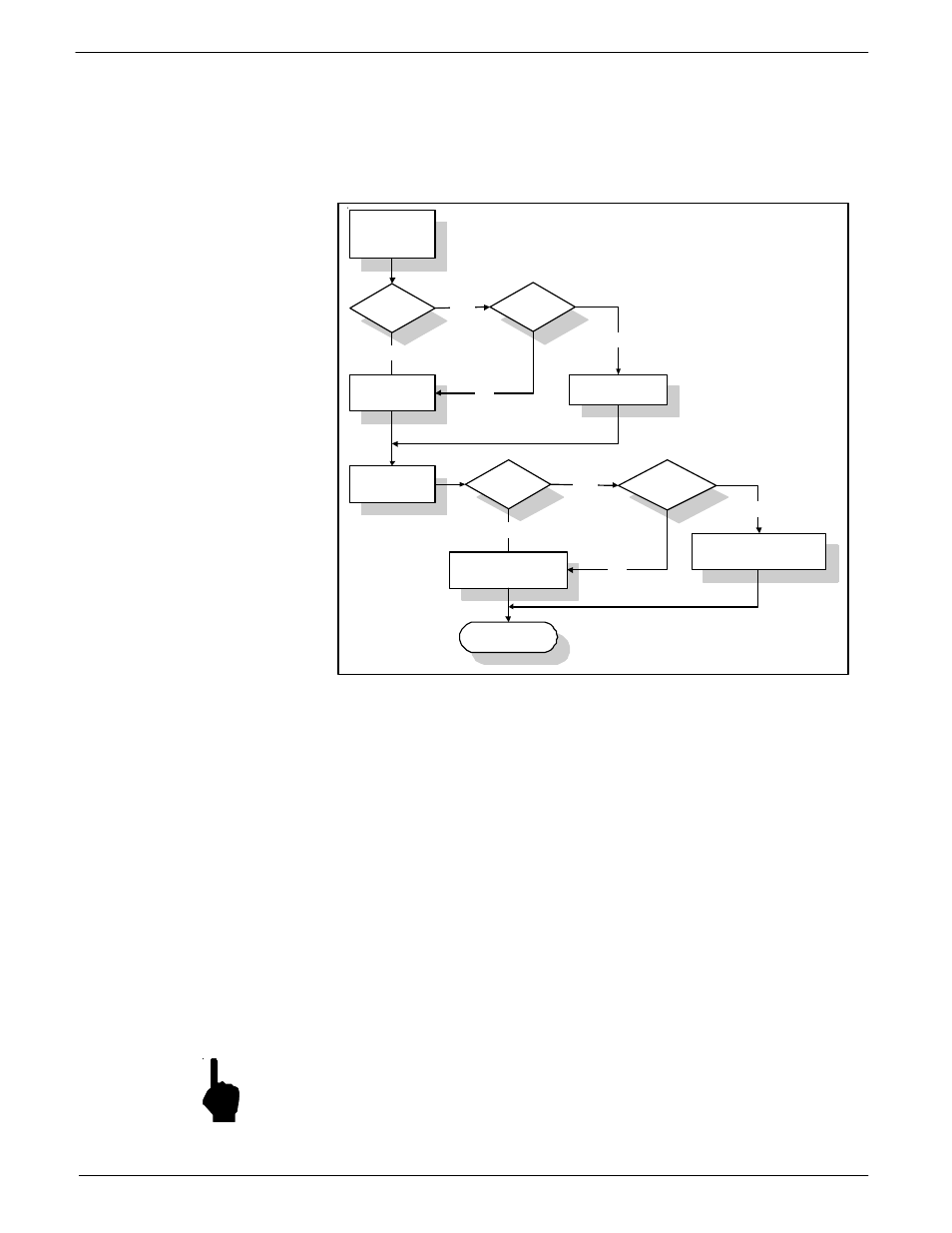
The flowmeter measures the applied current input, converts it to a digital value and makes a
correction to the measured flow rate. The corrected flow rate is used to drive the analog
outputs and manipulate the relays. The flow rate shown on the display is also the corrected
value. Figure 23 charts the process.
The auxiliary input port monitors the signal input level and converts it to a digital value. This
digital value can be displayed from menu level 2.4.3, the Auxiliary Test Input function.
w
To view the digital representation of the current input:
1.
Apply a current to the auxiliary input as shown in Figure 22.
2.
From the Main menu press 2. The 2.0 PORT SETUP menu title will appear.
3.
Press 4, the Aux Input option.
4.
Press 3, the Test Input option. The digital representation of the current input is
displayed on the second line.
The approximate relationship between current input and the digital value displayed in menu
level 2.4.3 is:
Digital Value = Current Input x 51.1
The digital value is used to manipulate the measured flow rate. This digital value is used to
calculate a factor that is multiplied by the measured flow rate. The factor is calculated using
the following relationship:
K
A
= A
1
+ (A
2
x s) + (A
3
s
2
) + (A
4
x s)
where
s = Digital Value
Ai = Correction Factor Coefficients ( i = 1 through 4 )
K
A
= Correction Factor
NOTE:
Ai is used for clarity in the manual. The flowmeter uses Fj as the Correction Factor
Coefficient.
The Auxiliary Input Equation coefficients are determined by the factory from the data
supplied at the time of order entry.
Figure 23 - Auxiliary Input Process
DR
Aux Input
Enb
Mode = DR?
DR
corr
= DR
DR
corr
= K
A
DR
Flow = f (DR
corr
)
Aux Input
Enb
Mode = Flow ?
Flow corr = Flow
Flow corr = K
A
Flow
YES
NO
NO
YES
YES
YES
NO
C00548-1
Output
Flow
corr
NO