Fluid Components International GF03 User Manual
Page 41
Doc. No. 06EN003352 Rev. B
3 7
Model GF03 Flow Meter
FLUID COMPONENTS INTERNATIONAL LLC http://www.fluidcomponents.com
3.
Verify that the ball valve on the probe assembly is closed. Remove the end cap and
attach the interconnecting hose and regulator assembly.
4.
Attach the calibration gas source to the inlet side of the regulator assembly.
5.
Slowly open the gas source regulator until the analog gauge in the Veri-cal regulator
assembly reads 125 psig, no gas should be flowing through the instrument at this time.
6.
Verify that the system is leak free.
7.
Obtain local atmospheric pressure. Look at the GF03 Veri-Cal calibration sheet and
calculate the pressure offset from the local atmospheric pressure and calibrated
atmospheric pressure.
Calibrated atm press – Local atm press = pressure offset
Add this offset to the Veri-Cal Baseline indicated pressure values in column 1 on the
calibration sheet to determine verification indicated pressure check values.
For example, if the calculated pressure offset is 1.40 psi and the first baseline indicated
pressure is 100 psig. The first verification check value of 101.40 should be dialed into
the Pressure displayed on the Transmitter display.
8.
Enter the Veri-cal menu on the Transmitter assembly (menu 7.4) Flow, Temperature and
Pressure will be displayed.
9.
Open the ball valve on the probe assembly and adjust the regulator so that the Pressure
display on the Transmitter display equals the first verification check value (101.40 in
the example).
10. Sustain this flow rate for 5 minutes to allow the instrument to come to thermal equilibrium.
11. Record the Indicated Flow, Temperature and Pressure.
12. Repeat this procedure for the remaining 3 indicated pressure check values. A consistent
flow across the thermowell should be held for a minimum of 5 minutes before values
are recorded.
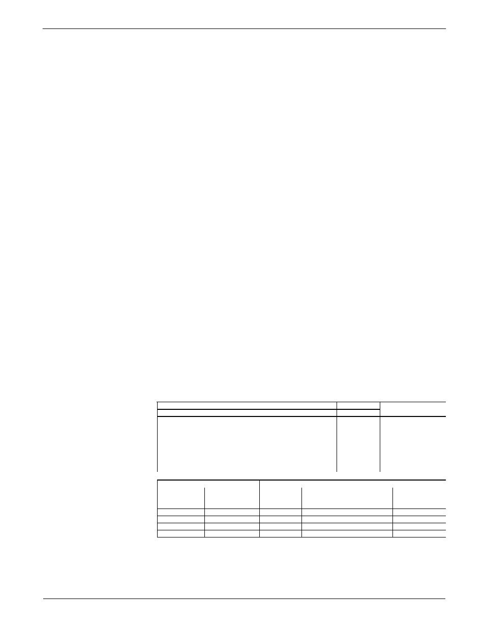
13. Record all values on the Veri-cal calibration sheet for reference and comparison during
the next in-situ verification check. An example of the calibration sheet is shown below.
Fluid
Temp
Nitrogen
AMBIENT
Test
Tech
L. Sales
Indicated
Pressure, psig
Atmospheric
pressure,
psia
Total
pressure,
psia
Indicated
(SFPS)
Veri-Cal Flow
Indicated
Temp
VDC, Pressure
Output
100
14.64
114.64
27.64
70.59
5.00
75
14.64
89.64
21.54
70.73
4.00
50.02
14.64
64.66
14.95
74.03
3.00
24.97
14.64
39.61
8.62
74.35
2.00
Field Check 1
Date:
Indicated
Pressure, psig
Atmospheric
pressure, psia
Total
pressure,
psia
Indicated
(SFPS)
Veri-Cal Flow
Indicated
Temp.
VDC “Raw”
Pressure
Output
Table 13 - Example of GF03 Calibration Sheet