Fluid Components International GF03 User Manual
Page 40
FLUID COMPONENTS INTERNATIONAL LLC http://www.fluidcomponents.com
Model GF03 Flow Meter
3 6
Doc. No. 06EN003352 Rev. B
The calibration functions of the flowmeter are contained in menu level 7.0. These functions
are not needed for general operation and setup of the flowmeter. With the exception of 7.1,
Show Delta R, these functions should be used only after consultation with a factory service
representative. Menu level 7.1 displays the RTD resistances and can be compared to
calibration resistances. This is useful for troubleshooting problems and is addressed in
Chapter 5, Troubleshooting.
w
To view RTD resistance values:
1.
Press 7, the Calibration option.
2.
Press 1, the Show Delta R option.
Calibration Functions
Menu 7.0
Veri-Cal
In-Situ Calibration
Verification
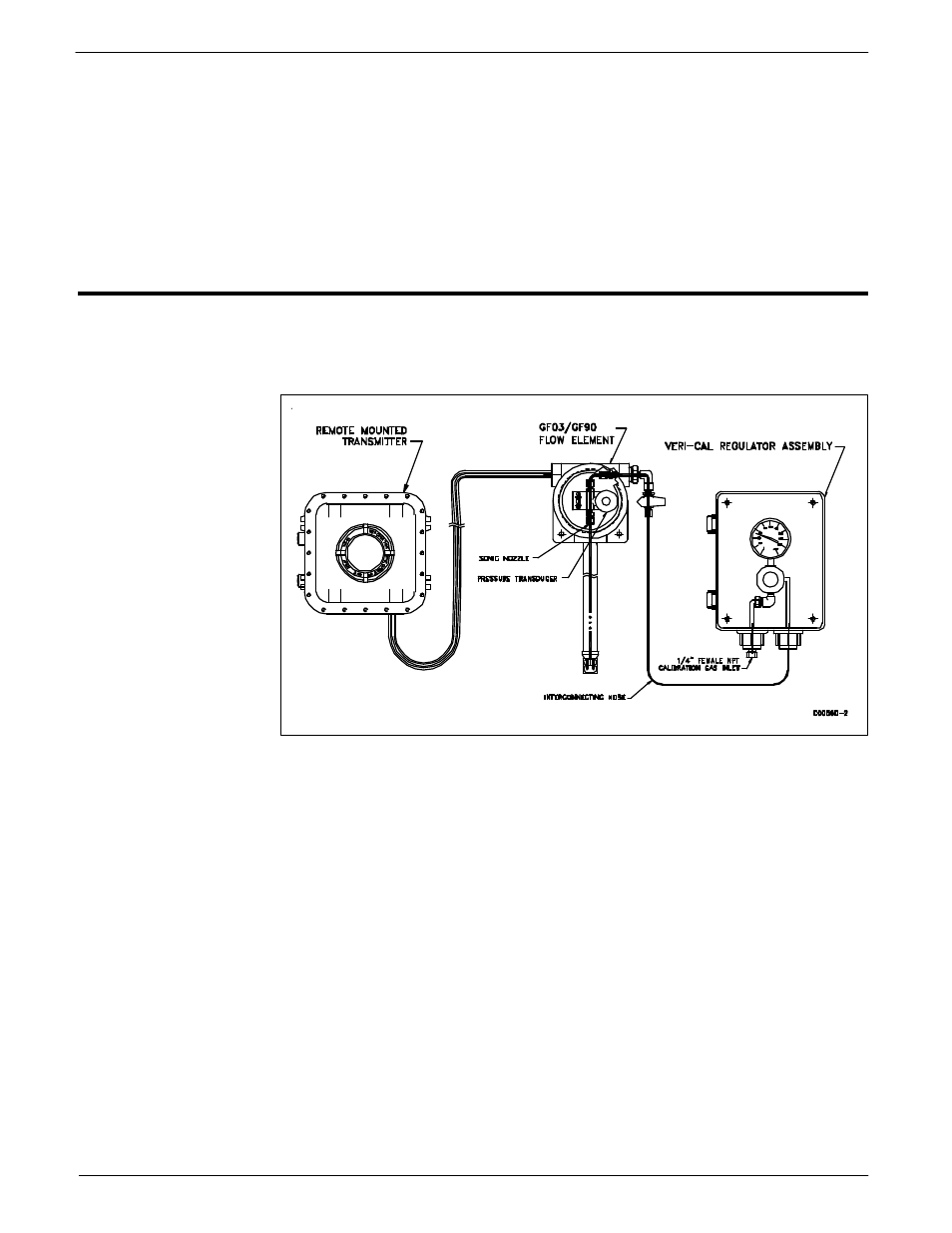
The GF03 has an optional Veri-Cal system that allows the user to check, or verify, the instruments
calibration without removing the flow element from the process installation. The diagram below
shows the Veri-Cal system.
The system consists of the Transmitter assembly, GF03 flow element with internal Veri-Cal
flow system, the Veri-Cal regulator assembly and interconnecting hose.
The Veri-cal flow system delivers a repeatable flow through a nozzle across the primary flow
element thermowells. This is done while the flow element is retracted out of the process flow
stream into the insertion packing gland assembly. The flow element orientation is leveled. An
inert gas controlled through a precision regulator on the inlet side of a sonic nozzle is then
injected across the thermowells. The factory calibration gas is typically Nitrogen, but other
gases maybe used.
Validation Check Procedure:
FCI recommends that this procedure be run at the Instruments commissioning to determine an
initial installed baseline verification calibration, and to record any installed offset from the factory
Veri-cal Basline.
1.
Loosen the packing nut assembly until the internal packing is lose enough to allow the
probe assembly to be retracted completly back into the insertion pipe assembly.
2.
Level orientation flat and tighten packing nut so probe assembly is secure.
Figure 28 - Veri-Cal System