Introduction, W-mount v-mount z-mount – Dynasonics TFX Ultra Transit Time Flow Meters User Manual
Page 9
INTRODUCTION
General
This transit time ultrasonic flow meter is designed to measure the fluid velocity of liquid within a closed conduit. The
transducers are a non-contacting, clamp-on type or clamp-around, which will provide benefits of non-fouling operation and
ease of installation.
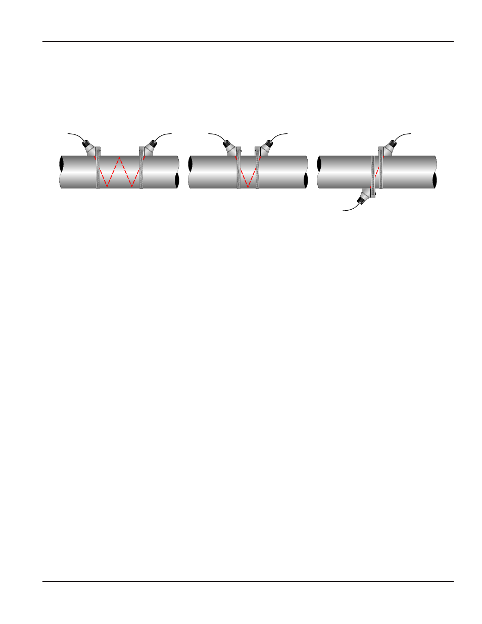
TOP VIEW
OF PIPE
W-Mount
V-Mount
Z-Mount
TOP VIEW
OF PIPE
TOP VIEW
OF PIPE
Figure 3: Ultrasound transmission
This family of transit time flow meters utilize two transducers that function as both ultrasonic transmitters and receivers.
The transducers are clamped on the outside of a closed pipe at a specific distance from each other. The transducers can be
mounted in V-Mount where the sound transverses the pipe two times, W-Mount where the sound transverses the pipe four
times, or in Z-Mount where the transducers are mounted on opposite sides of the pipe and the sound crosses the pipe once.
The selection of mounting method is based on pipe and liquid characteristics which both have an effect on how much signal
is generated. The flow meter operates by alternately transmitting and receiving a frequency modulated burst of sound energy
between the two transducers and measuring the time interval that it takes for sound to travel between the two transducers.
The difference in the time interval measured is directly related to the velocity of the liquid in the pipe.
Application Versatility
This flow meter can be successfully applied on a wide range of metering applications. The simple-to-program transmitter
allows the standard product to be used on pipe sizes ranging from 1/2 …100 inches (12…2540 mm)*. A variety of liquid
applications can be accommodated:
ultrapure liquids
cooling water
potable water
river water
chemicals
plant effluent
sewage
reclaimed water
others
Because the transducers are non-contacting and have no moving parts, the flow meter is not affected by system pressure,
fouling or wear. Standard transducers, DTTN and DTTL are rated to a pipe surface temperature of –40…250° F (–40…121° C).
DTTS small pipe transducers are rated from –40…185° F (–40…85° C). The DTTH high temperature transducers can operate
to a pipe surface temperature of –40 …350° F (–40…176° C) and the DTTC small pipe high temperature transducer will
withstand temperature of –40…250° F (–40…121° C).
OTE:
N
*All 1/2…1-1/2 in. small pipe transducers and 2 in. small pipe tubing transducer sets require the transmitter
be configured for 2 MHz and use dedicated pipe transducers. DTTL transducers require the use of the 500 kHz
transmission frequency. The transmission frequency is selectable using either the software utility or the
TFX Ultra keypad.
CE Compliance
The transmitter can be installed in conformance to CISPR 11 (EN 55011) standards. See the CE compliance drawings in the
APPENDIX
of this manual.
INTRODUCTION
Page 9
March 2014