Dynasonics TFX Ultra Transit Time Flow Meters User Manual
Page 66
Nex t>
< B a c k
Ca n c el
F i l e Op en . . .
F i l e Sa v e. . .
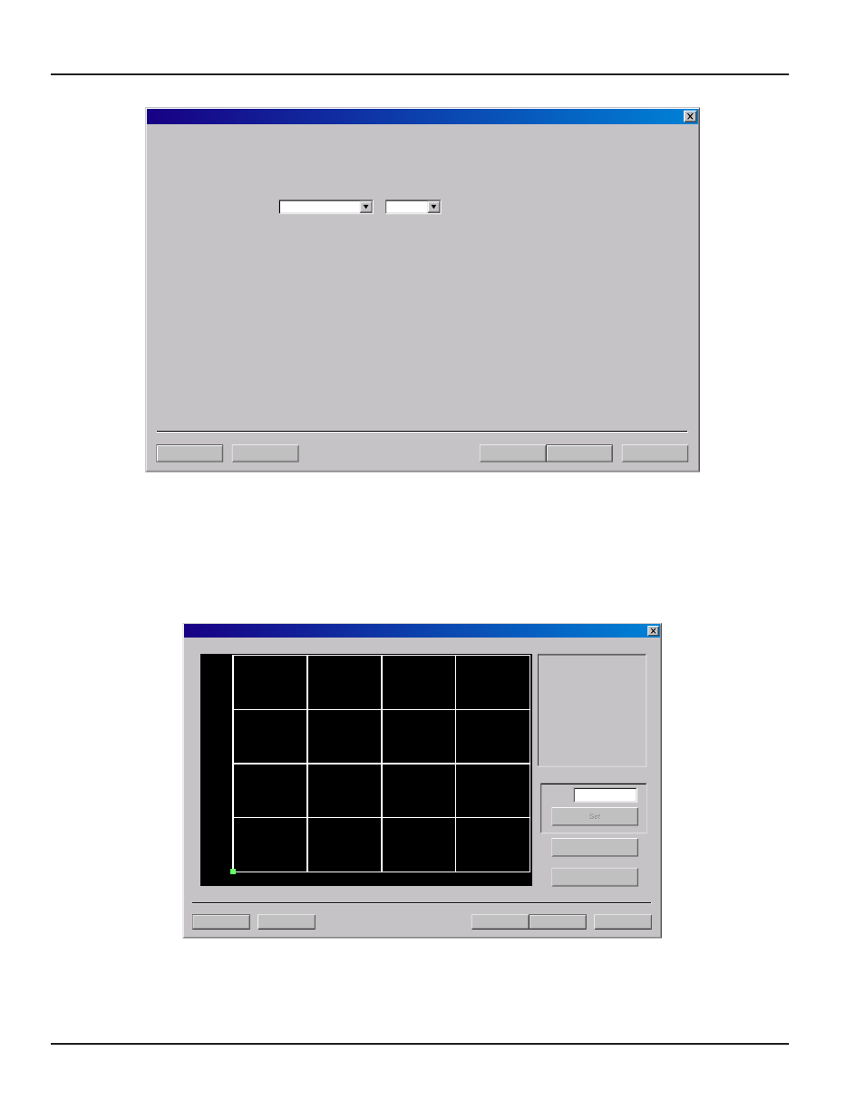
C a l i b r a t i o n ( Pa g e 2 o f 3 ) - G e n e r a l S e t u p
G a l l o n s
M i n
Flow Rate Units:
/
It i s a d v i sa b l e to F i l e Sa v e th e ex i sti n g c a l i b r a ti o n b ef o r e m o d i f y i n g i t. If th e F l o w R a te Un i ts sel ec ted o n th i s p a g e d o n o t
m a tc h th e F l o w R a te Un i ts u ti l i z ed f o r th e ex i sti n g d a ta p o i n ts c o l l ec ted o n Pa g e 3 o f 3, f l o w m ea su r em en t er r o r s c a n o c c u r .
To v i ew m ea su r em en t u n i ts, g o to Pa g e 3 o f 3 a n d p r ess E d i t. Th e Ca l i b r a ti o n Po i n ts E d i to r w i l l sh o w w h a t u n i ts
w er e u sed d u r i n g th e ex i sti n g c a l i b r a ti o n .
1) If n o d a ta ex i sts i n th e ed i to r , sel ec ti o n o f F l o w R a te Un i ts w i l l n o t i n f l u en c e m ea su r em en ts.
2) If n ew c a l i b r a ti o n p o i n ts a r e to b e en ter ed o n Pa g e 3 o f 3, i t i s a d v i sa b l e to r em o v e th e ex i sti n g c a l i b r a ti o n
p o i n ts u si n g th e Ca l i b r a ti o n Po i n ts E d i to r .
Figure 50: Calibration page 2 of 3
Page 3 of 3 as shown in
Figure 51
allows multiple actual flow rates to be recorded by the flow meter. To calibrate a point,
establish a stable, known flow rate (verified by a real-time primary flow instrument), enter the actual flow rate in the Flow
window and press Set. Repeat for as many points as desired.
OTE:
N
If only two points are to be used (zero and span), it is preferable to use the highest flow rate anticipated in normal
operation as the calibration point. If an erroneous data point is collected, the point can be removed by pressing Edit,
selecting the bad point and then selecting Remove.
Nex t>
< B a c k
Ca n c el
F i l e Op en . . .
F i l e Sa v e. . .
C a l i b r a t i o n ( Pa g e 2 o f 3 ) - G e n e r a l S e t u p
1) Pl ea se esta b l i sh a
r ef er en c e f l o w r a te.
1F PS / 0. 3M PS M i n i m u m .
2) E n ter th e r ef er en c e f l o w r a te
b el o w . ( Do n o t en ter 0)
3) W a i t f o r f l o w to sta b l i z e.
4 Pr ess th e Set b u tto n .
G
al/MIN
Delta Time
F l o w :
E x p o r t. . .
E d i t
Figure 51: Calibration page 3 of 3
Zero values are not valid for linearization entries. Flow meter zero is entered on Page 1 of 3. If a zero calibration point is
attempted, the following error message will be shown:
SETTING ZERO AND CALIBRATION
Page 66
March 2014