Flow tab – Dynasonics TFX Ultra Transit Time Flow Meters User Manual
Page 57
Transducer Spacing is a value calculated by the flow meter firmware that takes into account pipe, liquid, transducer and
mounting information. This spacing will adapt as these parameters are modified. The spacing is given in inches for English
units selection and millimeters for metric. This value is the lineal distance that must be between the transducer alignment
marks. Selection of the proper transducer mounting method is not entirely predictable and many times is an iterative process.
OTE:
N
This setting only applies to DTTN, DTTL, and DTTH transducers.
Transducer Flow Direction allows the change of the direction the meter assumes is forward. When mounting meters with
integral transducers, this feature allows upstream and downstream transducers to be electronically reversed, making upside
down mounting of the display unnecessary.
Pipe Material is selected from the pull-down list. If the pipe material utilized is not found in the list, select Other and enter the
actual pipe material Sound Speed and Roughness (much of this information is available at web sit
) for pipe relative roughness calculations.
Pipe O.D. and Wall Thickness are based on the physical dimensions of the pipe on which the transducers will be mounted.
Enter this value in inches for English units or millimeters for metric units.
OTE:
N
Charts listing popular pipe sizes have been included in the
APPENDIX
of this manual. Correct entries for pipe O.D. and
pipe wall thickness are critical to obtaining accurate flow measurement readings.
Liner Material is selected from the pull-down list. If the pipe liner material utilized is not included in the list, select Other and
enter liner material Sound Speed and Roughness (much of this information is available at web sites such as
www.ondacorp.
com/tecref_acoustictable.html
). See
page 41
for pipe liner relative roughness calculations.
Fluid Type is selected from a pull-down list. If the liquid is not found in the list, select Other and enter the liquid Sound Speed
and Absolute Viscosity into the appropriate boxes. The liquid’s specific gravity is required if mass measurements are to be
made, and the specific heat capacity is required for energy measurements.
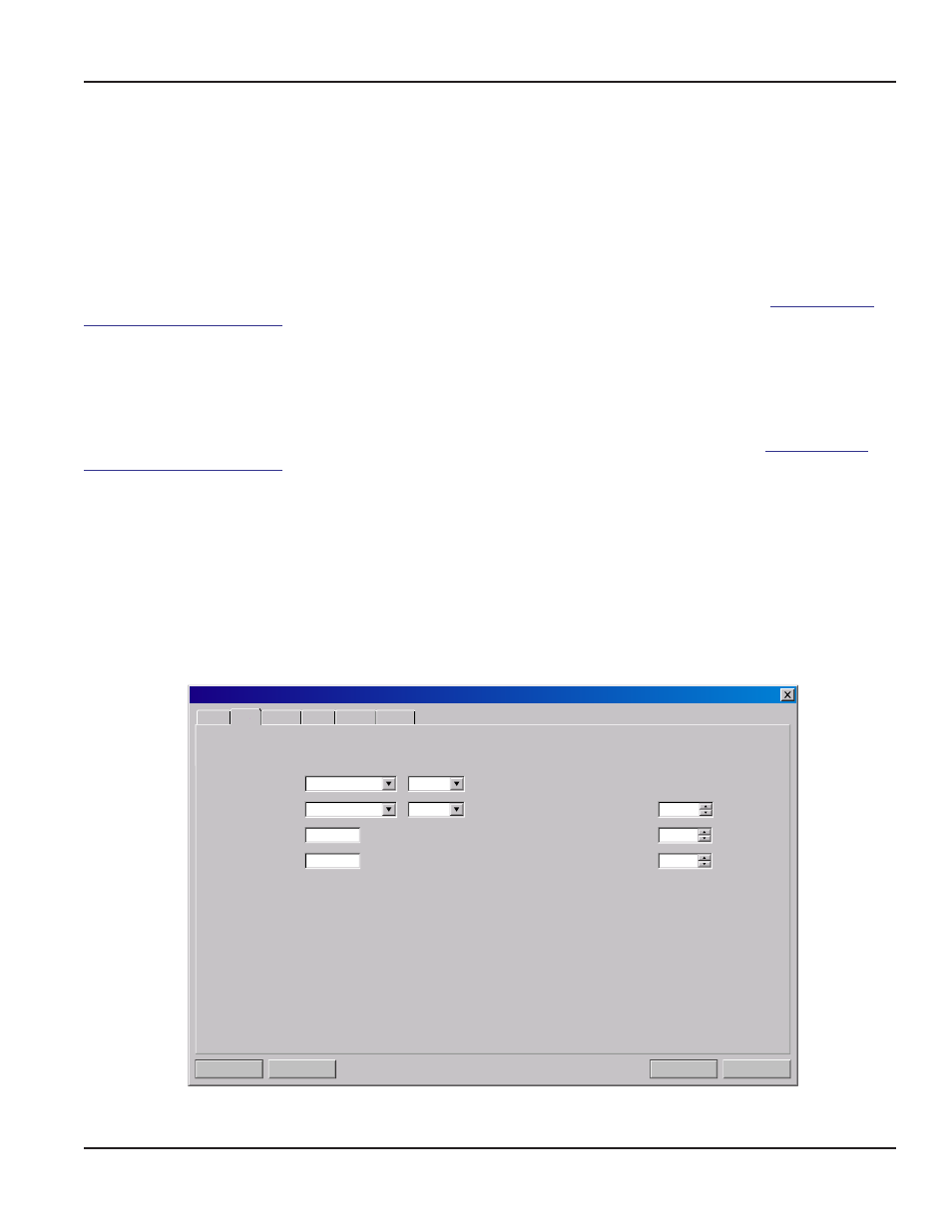
Flow Tab
Flow Rate Units are selected from the drop-down lists. Select an appropriate rate unit and time from the two lists. This entry
also includes the selection of Flow Rate Interval after the / sign.
Totalizer Units are selected from drop-down lists. Select an appropriate totalizer unit and totalizer exponent. The totalizer
exponents are in scientific notation and permit the eight digit totalizer to accumulate very large values before the totalizer
“rolls over” and starts again at zero.
Table 8
illustrates the scientific notation values and their respective decimal equivalents.
Do w n l o a d
Ca n c el
F i l e Op en . . .
F i l e Sa v e. . .
S y s t e m C o n f i g u r a t i o n
Display
Basic Flow Filtering Output Security
G a l l o n s
M i n
Flow Rate Units:
/
G a l l o n s
X 10
Totalizer Units:
0. 0
Min Flow:
Gal/M
Gal/M
400. 0
Max Flow:
Low Flow Cutoff:
Low Signal Cutoff:
%
%
Substitute Flow:
2
2
0
Figure 41: Flow tab
BASIC TAB
Page 57
March 2014