Top view of pipe – Dynasonics TFX Ultra Transit Time Flow Meters User Manual
Page 27
8. A minimum signal strength of 5 is acceptable as long as this signal level is maintained under all flow conditions.
On certain pipes, a slight twist to the transducer may cause signal strength to rise to acceptable levels. Certain pipe and
liquid characteristics may cause signal strength to rise to greater than 98. The problem with operating this meter with very
high signal strength is that the signals may saturate the input amplifiers and cause erratic readings. Strategies for lowering
signal strength would be changing the transducer mounting method to the next longest transmission path. For example,
if there is excessive signal strength and the transducers are mounted in a Z-Mount, try changing to V-Mount or W-Mount.
Finally you can also move one transducer slightly off line with the other transducer to lower signal strength.
9. Secure the transducer with a stainless steel strap or other fastener.
Mounting Track Installation
1. A convenient transducer mounting track can be used for pipes that have outside diameters between two and ten inches
(50 … 250 mm). If the pipe is outside of that range, select a V-Mount or Z-Mount mounting method.
2. Install the single mounting rail on the side of the pipe with the stainless steel bands provided. Do not mount it on the top
or bottom of the pipe. Orientation on vertical pipe is not critical. Ensure that the track is parallel to the pipe and that all
four mounting feet are touching the pipe.
3. Slide the two transducer clamp brackets towards the center mark on the mounting rail.
4. Place a single bead of couplant, approximately 1/2 inch (12 mm) thick, on the flat face of the transducer. See
Figure 12
.
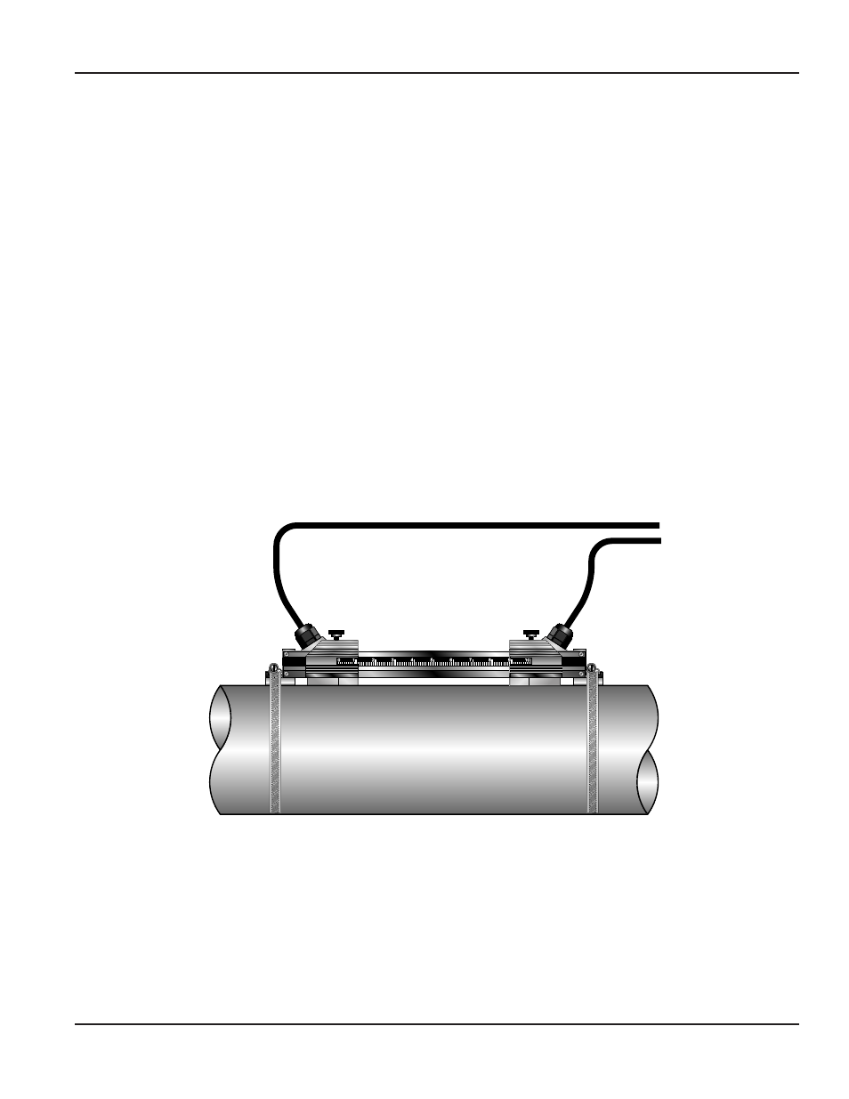
5. Place the first transducer in between the mounting rails near the zero point on the scale. Slide the clamp over the
transducer. Adjust the clamp/transducer such that the notch in the clamp aligns with zero on the scale. See
Figure 22
.
6. Secure with the thumb screw. Ensure that the screw rests in the counter bore on the top of the transducer. (Excessive
pressure is not required. Apply just enough pressure so that the couplant fills the gap between the pipe and transducer.)
7. Place the second transducer in between the mounting rails near the dimension derived in the transducer spacing section.
Read the dimension on the mounting rail scale. Slide the transducer clamp over the transducer and secure with the
thumb screw.
Top View
of Pipe
Figure 22: Mounting track installation
V-MOUNT AND W-MOUNT INSTALLATION
Page 27
March 2014