Filtering tab – Dynasonics TFX Ultra Transit Time Flow Meters User Manual
Page 59
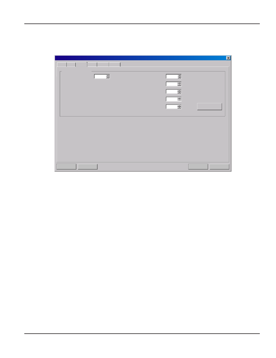
Filtering Tab
The Filtering tab contains several filter settings for the flow meter. These filters can be adjusted to match response times and
data “smoothing” performance to a particular application.
Do w n l o a d
Ca n c el
F i l e Op en . . .
F i l e Sa v e. . .
S y s t e m C o n f i g u r a t i o n
Display
Basic
Flow Filtering Output Security
%
Flow Filter (Damping):
%
80
Time Domain Filter:
8
Advanced Filter Settings:
Flow Filter Hystersis:
5
psec
Flow Filter Min Hystersis:
303
Bad Data Rejection:
3
Flow Filter Sensitivity:
3
F a c to r y Def a u l ts
Figure 42: Filtering tab
Time Domain Filter (range 1…256) adjusts the number of raw data sets (the wave forms viewed on the software Diagnostics
Screen) that are averaged together. Increasing this value will provide greater damping of the data and slow the response time
of the flow meter. Conversely, lowering this value will decrease the response time of the meter to changes in flow/energy rate.
This filter is not adaptive, it is operational to the value set at all times.
OTE:
N
The flow meter completes a measurement in approximately 350…400 mS. The exact time is pipe size dependent.
Flow Filter (Damping) establishes a maximum adaptive filter value. Under stable flow conditions (flow that varies less than the
Flow Filter Hysteresis entry), this adaptive filter will increase the number of successive flow readings that are averaged together
up to this maximum value. If flow changes outside of the flow filter hysteresis window, the filter adapts by decreasing the
number of averaged readings and allows the meter to react faster.
The damping value is increased to increase stability of the flow rate readings. Damping values are decreased to allow the flow
meter to react faster to changing flow rates. The factory settings are suitable for most installations. Increasing this value tends
to provide smoother steady-state flow readings and outputs.
Flow Filter Hysteresis creates a window around the average flow measurement reading allowing small variations in flow
without changing the damping value. If the flow varies within that hysteresis window, greater display damping will occur up
to the maximum values set by the flow filter entry. The filter also establishes a flow rate window where measurements outside
of the window are examined by the Bad Data Rejection filter. The value is entered as a percentage of actual flow rate.
For example, if the average flow rate is 100 gpm and the Flow Filter Hysteresis is set to 5%, a filter window of 95…105 gpm is
established. Successive flow measurements that are measured within that window are recorded and averaged in accordance
with the Flow Filter Damping setting. Flow readings outside of the window are held up in accordance with the Bad Data
Rejection filter.
Flow Filter MinHysteresis sets a minimum hysteresis window that is invoked at sub 0.25 fps (0.08 mps) flow rates, where the “of
rate” flow filter hysteresis is very small and ineffective. This value is entered in pico-seconds (ρsec) and is differential time. If
very small fluid velocities are to be measured, increasing the flow filter minhysteresis value can increase reading stability.
BASIC TAB
Page 59
March 2014