Dynasonics TFX Ultra Transit Time Flow Meters User Manual
Page 8
Pipe Preparation and Transducer Mounting
DTTN, DTTL, and DTTH Transducers
1. Place the flow meter in signal strength measuring mode. This
value is available on the flow meters display Service Menu or in
the data display of the software utility.
2. The pipe surface, where the transducers are to be mounted,
must be clean and dry. Remove scale, rust or loose paint
to ensure satisfactory acoustic conduction. Wire brushing
the rough surfaces of pipes to smooth bare metal may also
be useful. Plastic pipes do not require preparation other
than cleaning.
3. Apply a single 1/2 in. (12 mm) bead of acoustic couplant grease
to the upstream transducer and secure it to the pipe with a
mounting strap.
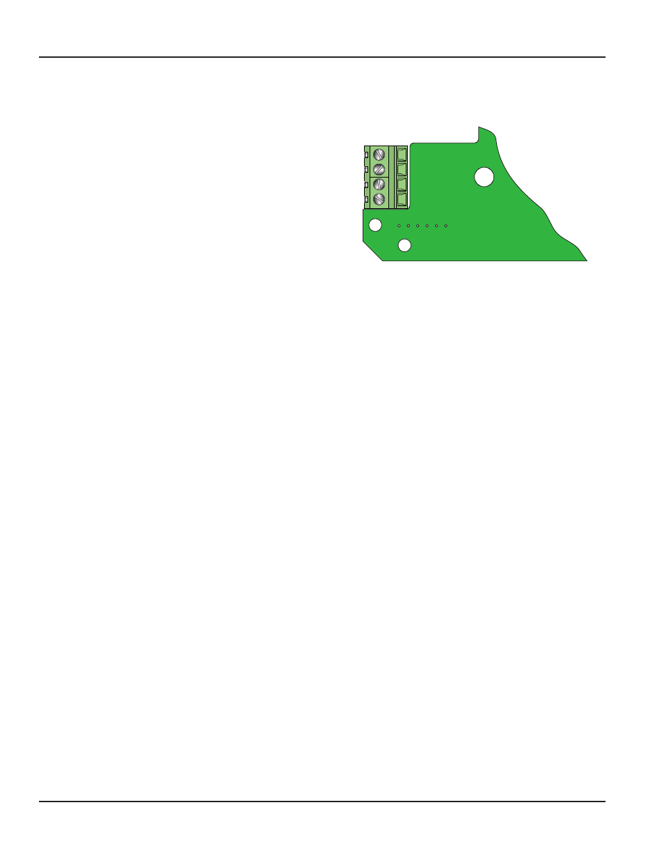
Downstream+
Downstream-
Upstream-
Upstream+
Figure 2: Transducer connections
4. Apply acoustic couplant grease to the downstream transducer and press it onto the pipe using hand pressure at the lineal
distance calculated in
Transducer Location on page 7
.
5. Space the transducers according to the recommended values found during programming or from the software utility.
Secure the transducers with the mounting straps at these locations.
DTTS and DTTC Transducers
1. Place the flow meter in signal strength measuring mode. This value is available on the flow meter’s display Service Menu or
in the data display of the software utility.
2. The pipe surface, where the transducers are to be mounted, must be clean and dry. Remove scale, rust or loose paint to
ensure satisfactory acoustic conduction. Wire brushing the rough surfaces of pipes to smooth bare metal may also be
useful. Plastic pipes do not require preparation other than cleaning.
3. Apply a single 1/2 in. (12 mm) bead of acoustic couplant grease to the top half of the transducer and secure it to the pipe
with bottom half or U-bolts.
4. Tighten the nuts so that the acoustic coupling grease begins to flow out from the edges of the transducer and from the
gap between the transducer and the pipe.
MPORTANT
I
Do not over tighten.
Startup
Initial Settings and Power-up
1. Apply power to the transmitter.
2. Verify that SIG STR is greater than 5.0.
3. Input proper units of measure and I/O data.
QUICK-START OPERATING INSTRUCTIONS
Page 8
March 2014