Transducer – Dynasonics TFX Ultra Transit Time Flow Meters User Manual
Page 56
OTE:
N
This address does not set the Modbus TCP/IP, EtherNet/IP, BACnet address. That is set via the web page interface that
is integrated into the Ethernet port.
OTE:
N
Do not confuse the MODBUS address with the device address as seen in the upper left-hand corner of the display.
The Device Addr is included for purposes of backward compatibility of first generation flow meter products. The
device address has no function and will not change when used with this flow meter family.
Transducer
Transducer Type selects the transducer that will be connected to the flow meter. Select the appropriate transducer type from
the drop-down list. This selection influences transducer spacing and flow meter performance, so it must be correct. If you are
unsure about the type of transducer to which the flow meter will be connected, consult the shipment packing list or call the
manufacturer for assistance.
OTE:
N
A change of transducer type will cause a system configuration error 1002: Sys Config Changed to occur. This error will
clear when the microprocessor is reset or power is cycled on the flow meter.
Transducer Mount selects the orientation of the transducers on the piping system. See
TRANSDUCER INSTALLATION
in
this manual and
Table 2
for detailed information regarding transducer mounting modes for particular pipe and liquid
characteristics. Whenever transducer mount is changed, a download command and subsequent microprocessor reset or flow
meter power cycle must be conducted.
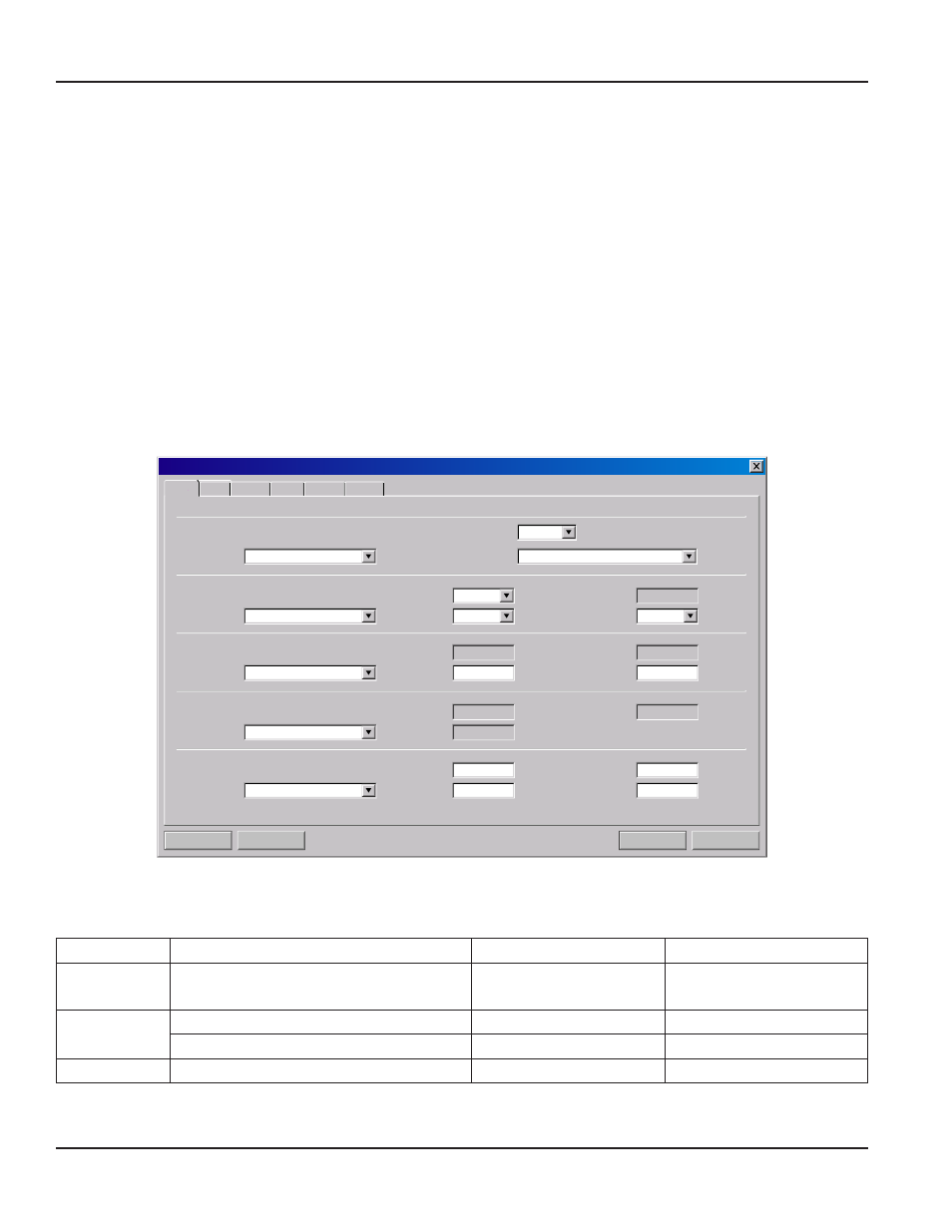
Do w n l o a d
Ca n c el
F i l e Op en . . .
F i l e Sa v e. . .
S y s t e m C o n f i g u r a t i o n
Flow
Basic
Display
Basic
Flow Filtering Output Security
DTTN Cl a m p -On
Z
1 M H z
1. 33 i n
F o r w a r d
Ca r b o n Steel
1059 8. 00
1. 5
0. 000150
0. 218
Oth er
1
1
8061
1
No n e
0. 0
0. 0
0. 0
E n g l i sh
Cu sto m
7
General
Transducer
Pipe
Liner
Fluid
Units:
Type:
Material:
Material:
Standard Configurations:
MODBUS Address:
Flow Direction:
Wall Thickness:
in
cp
FPS
in
in
FPS
FPS
Type:
Frequency:
Pipe OD:
Thickness:
Spec. Gravity:
Sound Speed:
Sound Speed:
Sound Speed:
Mount:
Spec. Heat Capacity:
Abs. Viscosity:
Roughness:
Roughness:
Spacing:
Figure 40: Basic tab
Transducer Frequency permits the meter to select a transmission frequency for the various types of transducers that can be
utilized. In general, the larger the pipe the slower the transmission frequency needs to be to attain a good signal.
Frequency
Transducers
Transmission Modes
Pipe Size and Type
2 MHz
All 1/2…1-1/2 in. Small Pipe and Tube
2 in. Tubing
Selected by Firmware
Specific to Transducer
1 MHz
2 in. ANSI Pipe and Copper Tube
Selected by Firmware
Specific to Transducer
Standard and High Temp
W, V, and Z
2 in. and Greater
500 kHz
Large Pipe
W, V, and Z
24 in. and Greater
Table 12: Transducer Frequencies
BASIC TAB
Page 56
March 2014