Wiring to meter, Installation of insertion rtd’s, Rc u s – Dynasonics TFX Ultra Transit Time Flow Meters User Manual
Page 35: Product service, Minc o
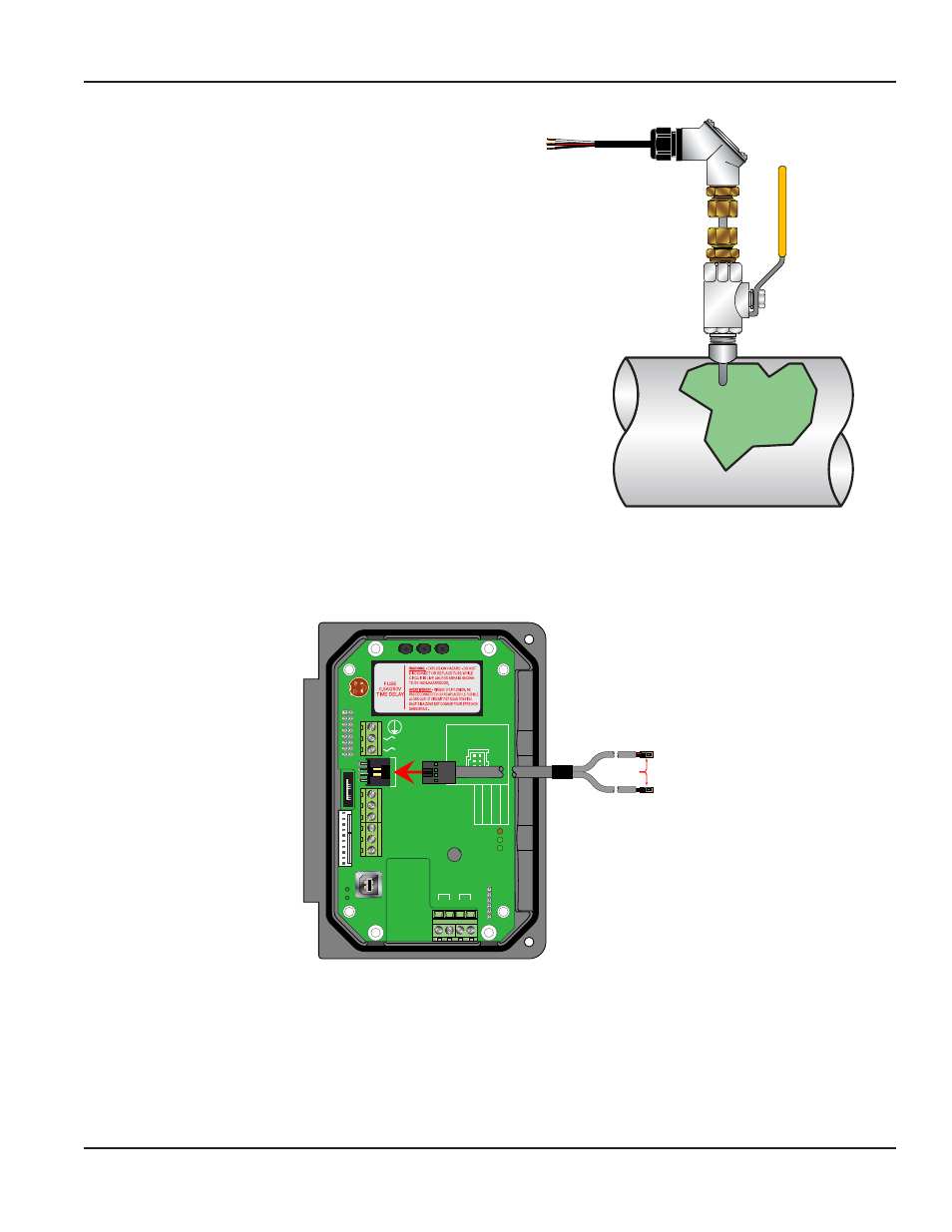
WIRING TO METER
After the RTDs have been mounted to the pipe, route the cable back to the flow meter through the middle hole in the
enclosure. Connection to the meter is accomplished by inserting the RTD connector into the mating connector on the circuit
board. Be sure that the alignment tab on the RTD cable is up.
95 - 264 VAC
AC Neutral
Signal Gnd.
4-20 mA Out
Reset Total
RS485 Gnd
RS485 A(-)
RS485 B(+)
D
ownstr
eam
Upstr
eam
+
+
- -
RTD 1 RTD 2
TEMP
. SE
T
0 t
o 50°C
0 t
o 100°C
-40 t
o 200°C
Modbus
TFX Rx
TFX Tx
Exc.
Sig.
Gnd.
Shield
Exc.
Sig.
Gnd.
Shield
W
R
C
U
S
1500mA250V
D
VE
372
R
C US
E167432
$
TUV
PRODUCT SERVICE
RoHS
AC IN : 100-240VAC,50/60Hz
DC OUT :
+15V / 0.3A
PWC - 1 5 E
0.15A
R2807
w w w . a s t r o d y n e . c o m
- Vo
+ Vo
A C L
A C N
s t r o d y n e
R ETU R N L IN E
R TD # 2
MINC
O
S U PPL Y L IN E
R TD # 1
MINC
O
RTD’s
Figure 36: Connecting RTDs
INSTALLATION OF INSERTION RTD’S
Insertion RTDs are typically installed through 1/4 inch (6 mm)
compression fittings and isolation ball valves. Insert the RTD
sufficiently into the flow stream such that a minimum of 1/4 inch
(6 mm) of the probe tip extends into the pipe diameter.
RTDs should be mounted within ±45 degrees of the side of a
horizontal pipe. On vertical pipes the orientation is not critical.
Route the RTD cables back to the flow meter and secure the cable
so that it will not be pulled on or abraded inadvertently.
If the cables are not long enough to reach the flow meter route
the cables to an electrical junction box and add additional cable
from that point. Use three-wire shielded cable, such as Belden®
9939 or equal, for this purpose.
OTE:
N
Adding cable adds to the resistance the meter reads
and may have an effect on absolute accuracy. If
cable is added, ensure that the same length is added
to both RTDs to minimize errors due to changes in
cable resistance.
Figure 35: Insertion style RTD installation
INSTALLATION OF INSERTION RTD’S
Page 35
March 2014