Appendix, Setting zero and calibration, Basic menu page 2 page 3 – Dynasonics TFX Ultra Transit Time Flow Meters User Manual
Page 69: Page 1
APPENDIX
A
cr
ylic
A
luminum
Br
ass (Na
val)
Car
bon S
teel
Cast I
ron
Copp
er
D
uc
tile I
ron
Fib
er
glass-Ep
ox
y
G
lass P
yr
ex
Nylon HD P
oly
eth
ylene
LD P
oly
eth
ylene
Polypr
op
ylene
PVC
C
PVC
PVDF St S
teel 302/303
St S
teel 304/316
St S
teel 410
St S
teel 430
PFR Titanium O
ther
PIPE M
AT
Pipe M
at
er
ial
English (FPS) M
etric (MPS)
PIPE SS
Pipe S
ound Speed
Numeric En
tr
y
PIPE R
Rela
tiv
e R
oughness
English (I
nches)
M
etric (mm)
LINER T
Pipe
Liner T
hick
ness
English M
etric
UNIT
S
Pr
og
ramming Units
V W Z
XDCR MNT
Tr
ansduc
er M
oun
ting
English (I
nches)
M
etric (mm)
PIPE OD
Pipe O
utside Diamet
er
English (I
nches)
M
etric (mm)
PIPE W
T
Pipe
W
all T
hick
ness
500 KH
z
1 MH
z
2 MH
z
XDUCR HZ
Tr
ansduc
er F
requenc
y
English (FPS) M
etric (MPS)
LINER SS
Pipe Liner S
ound Speed
W
at
er T
ap
Se
w
age
A
cet
one
A
lc
ohol
A
mmonia
Benz
ene
Ethanol Eth
ylene G
ly
col
G
asoline
G
ly
cerin
Isopr
op
yl A
lc
ohol
Ker
osene
M
ethanol
O
il D
iesel
O
il Hy
dr
aulic
(p
etr
o-base)
O
il L
ubric
ating
O
il M
ot
or
(SAE 20/30)
W
at
er D
istilled
W
at
er S
ea
O
ther
FL T
YPE
Fluid T
ype
Tar Ep
ox
y
Rubb
er
M
or
tar
Polypr
op
ylene
Poly
st
yr
ene
HDPE LDPE Teflon (PF
A
)
Eb
onit
e
O
ther
LINER T
YPE
Pipe Liner M
at
er
ial
English (FPS) M
etric (MPS)
FL
UID SS
Fluid S
ound Speed
CPS
FL
UID VI
Fluid V
isc
osit
y
Numeric En
tr
y
SP GR
V
TY
Specific Gr
avit
y
Numeric En
tr
y
SP HEA
T
Nominal Hea
t C
apacit
y
English (I
nches)
M
etric (mm)
N
ot
e:
T
his v
alue is calcula
ted
by fir
m
w
ar
e.
XDC SP
A
C
Tr
ansduc
er Spacing
Sec M
in
H
our
D
ay
RA
TE INT
Rat
e I
nt
er
va
l
G
allons
Lit
ers
MG
al
Cubic Ft Cubic M
e
A
cr
e Ft
O
il B
arr
(42 G
al)
Liq B
arr
(31.5 G
al)
Feet M
et
ers
LB KG
1
BT
U
1
MB
TU
1
MMB
TU
1
To
n
1
kJ
1
kWH
1
MWH
TO
TL UNT
Total Units
E-1
(-10)
E0
(X1)
E1
(X10)
E2
(X100)
E3
(X1,000)
E4
(X10,000)
E5
(X100,000)
E6
(X1,000,000)
TO
TL E
Totaliz
er Exponen
t
Numeric En
tr
y
MIN R
ATE
M
inimum F
lo
w R
at
e
Numeric En
tr
y
M
A
X R
ATE
M
aximum F
lo
w R
at
e
Numeric En
tr
y
FL C-
OFF
Lo
w F
lo
w C
ut
off
Numeric En
tr
y
D
AMP PER
Damping P
er
cen
tage
Numeric En
tr
y (1-126)
ADDRESS
M
ulti-Dr
op D
evic
e A
ddr
ess
Numeric En
tr
y
LINER R
Liner R
oughness
For
w
ar
d
Re
verse
FL
O
W DIR
Flo
w Dir
ec
tion
G
allons
Lit
ers
MG
al
Cubic Ft Cubic M
e
A
cr
e Ft
O
il B
arr
(42 G
al)
Liq B
arr
(31.5 G
al)
Feet M
et
ers
LB KG
1
BT
U
1
MB
TU
1
MMB
TU
1
To
n
1
kJ
1
kWH
1
MWH
RA
TE UNT
Ra
te Units
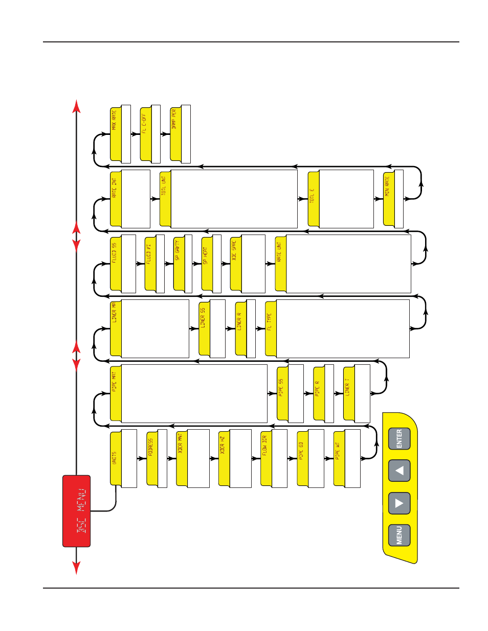
BASIC MENU
Page 2
Page 3
1
These hea
t flo
w
measur
emen
ts only
appear when R
TD is
chosen in the O
utput 2
menu
.
Page 1
Figure 54: Menu map page1
SETTING ZERO AND CALIBRATION
Page 69
March 2014