Transducer connections, Rc u s, Pr oduct ser vice – Dynasonics TFX Ultra Transit Time Flow Meters User Manual
Page 14
OTE:
N
Use NEMA 4 [IP-65] rated fittings/plugs to maintain the watertight integrity of the enclosure. Generally, the right
conduit hole (viewed from front) is used for power, the left conduit hole for transducer connections, and the center
hole is utilized for I/O wiring.
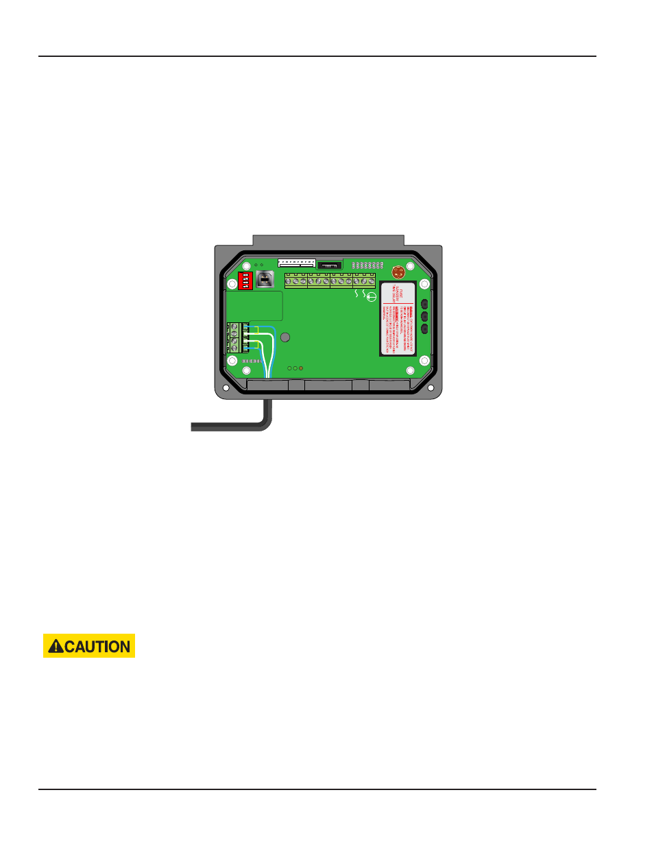
Transducer Connections
To access terminal strips for wiring, loosen the two screws in the enclosure door and open.
Guide the transducer terminations through the transmitter conduit hole located in the bottom-left of the enclosure. Secure
the transducer cable with the supplied conduit nut (if flexible conduit was ordered with the transducer).
The terminals within flow meter are of a screw-down barrier terminal type. Connect the appropriate wires at the
corresponding screw terminals in the transmitter. Observe upstream and downstream orientation and wire polarity. See
Figure 5
.
Downstream
Upstream
+
+
-
-
M
odbus
TFX Rx
TFX T
x
Sig
nal Gnd
.
Con
tr
ol 1
Con
tr
ol 2
Frequenc
y O
ut
4-20 mA O
ut
Reset T
otal
RS485 Gnd
RS485 A(-)
RS485 B(+)
95 - 264
VA
C
AC Neutr
al
W
R
C
U
S
1500mA250V
D
VE
372
R
C US
E167432
$
TUV
PR
ODUCT SER
VICE
RoHS
AC
IN
: 100-240V
AC
,50/60Hz
DC OUT
:
+15V / 0.3A
PWC
-1
5
E
0.15A
R2807
w
w
w
.a
s
tr
o
d
y
n
e
.c
o
m
-Vo
+
Vo
A
C
L
A
C
N
s
tr
o
d
y
n
e
1
2
3
4
O
N
To Transducers
Downstream
Upstream
+
+
-
-
Figure 5: Transducer connections
OTE:
N
Transducer cables have two possible wire colors. For the blue and white combination the blue wire is positive (+) and
the white wire is negative (-). For the red and black combination the red wire is positive (+) and the black
wire is negative (-).
OTE:
N
The transducer cable carries low level, high frequency signals. In general, it is not recommended to add additional
length to the cable supplied with the transducers. If additional cable is required, contact the factory to arrange an
exchange for a transducer with the appropriate length of cable. Cables 100…990 feet (30…300 meters) are available
with RG59 75 Ohm coaxial cable. If additional cable is added, ensure that it is the same type as utilized on the
transducer. Twinaxial (blue and white conductor) cables can be lengthened with like cable to a maximum overall
length of 100 feet (30 meters). Coaxial cables can be lengthened with RG59 75 Ohm cable and BNC connectors to
990 feet (300 meters).
Connect power to the screw terminal block in the transmitter. See
Figure 6
and
Figure 7
. Utilize the conduit hole on the right
side of the enclosure for this purpose. Use wiring practices that conform to local and national codes such as The National
Electrical Code Handbook in the U.S.
ANY OTHER WIRING METHOD MAY BE UNSAFE OR CAUSE IMPROPER OPERATION OF THE INSTRUMENT.
OTE:
N
This instrument requires clean electrical line power. Do not operate this unit on circuits with noisy components (i.e.,
fluorescent lights, relays, compressors, or variable frequency drives). The use of step down transformers from high
voltage, high amperage sources is also not recommended. Do not to run signal wires with line power within the
same wiring tray or conduit.
TRANSMITTER INSTALLATION
Page 14
March 2014