Dynasonics TFX Ultra Transit Time Flow Meters User Manual
Page 62
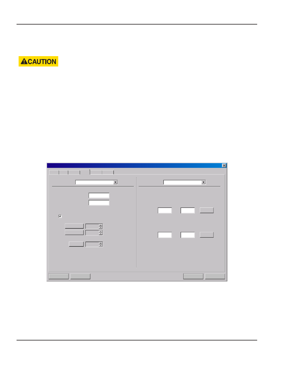
Channel 2 - RTD Configuration [for energy units Only]
OTE:
N
The Channel 2 Menu is used to configure model specific I/O options. The flow only meter presents a different set of
parameters than the energy meter.
IT IS POSSIBLE TO CHOOSE OPTIONS PERTAINING ONLY TO THE FLOW ONLY MODEL WHEN AN ENERGY METER IS
PRESENT. THE OPPOSITE IS ALSO TRUE. THE PROPER MENU TYPE MUST BE CHOSEN FOR THE ACTUAL METER. IF THIS
CAUTION ISN’T FOLLOWED, THE OUTPUTS OR METER READINGS WILL BE UNPREDICTABLE.
Inputs from two 1000 Ohm platinum RTD temperature sensors allow the measurement of energy delivered in liquid heating
and cooling systems.
The values used to calibrate the RTD temperature sensors are derived in the laboratory and are specific to a specific RTD.
The RTDs on new units come with the calibration values already entered into the energy meter and should not need to
be changed.
Field replacement of RTDs is possible thru the use of the keypad or the software. If the RTDs were ordered from the
manufacturer, they will come with calibration values that need to be loaded into the energy meter.
RTD Calibration Procedure:
1. Enter the calibration values for RTD #1 A and RTD #1 B followed by RTD #2 A and RTD #2 B.
2. Double-click Download to send the values to memory.
3. Turn the power off and then back on to the flow meter to enable the changes to take effect.
Do w n l o a d
Ca n c el
F i l e Op en . . .
F i l e Sa v e. . .
S y s t e m C o n f i g u r a t i o n
Display
Basic
Flow Filtering Output Security
4-20m A / F r eq u en c y
Channel 1:
0
Flow at 4mA / 0Hz:
Gal/M
400
Flow at 20mA / 1KHz:
Gal/M
Calibration/Test
Test
Calibration
4 m A
20 m A
32
3837
Test
4
R TD
Channel 2:
RTD #1:
A:
B:
Ca l i b r a te
0. 0000
0. 0000
RTD #2:
A:
B:
Ca l i b r a te
0. 0000
0. 0000
Figure 44: Channel 2 input (RTD)
New, non-calibrated RTDs will need to be field calibrated using an ice bath and boiling water to derive calibration values. This
procedure is outlined in the
APPENDIX
of this manual.
BASIC TAB
Page 62
March 2014