Volume control (vol), Telephone tx (dmp 128 c p and dmp 128 c p at only), Volume control (vol) telephone tx (dmp 128 c p and – Extron Electronics DMP 128 User Guide User Manual
Page 68: Dmp 128 c p at only)
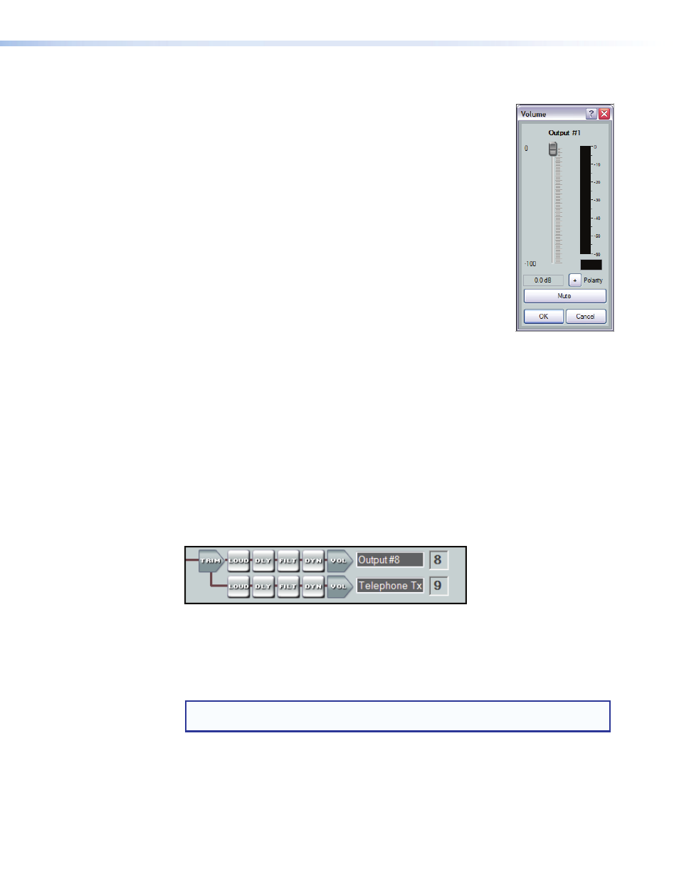
Volume control (VoL)
Each output channel volume block provides a mono long-throw
fader and a volume setting readout (in dB) below the fader. Volume
level is adjustable with the slider or by entering the desired level
directly into the volume setting readout in 0.1 dB increments.
Clicking the fader handle or clicking within the fader area brings
focus to the fader. The input signal level can be adjusted using any
of the following methods:
•
Click and hold the fader handle, then drag it to desired level in
1.0 dB steps.
•
Click or
in 1 dB steps.
(decrease) the level in 5 dB steps.
•
Click in or tab to the level readout field. Type a new value, then
press
The default setting is unmuted, at 0 dB attenuation. A peak meter
displays the real-time audio level from – 60 to 0 dBFS.
Click OK to accept settings and close the dialog box. Click Cancel to ignore changes
and close the dialog box.
The output volume control provides level control for each output. The output control is a
trim control adjustable from – 100.0 to 0 dB. The default setting is unity gain (0.0 dB).
The Polarity button, allows the polarity of the wires connected to the audio connectors
(+/tip and -/ring) to be flipped in order to easily correct for miswired connectors.
The Mute button silences the post-meter audio output. When the audio output is muted,
the mute button lights red, and red indicators in the block turn on.
If the output has been grouped with other inputs or outputs, the group number is
indicated on the right side of this button (see
telephone tx (DMP 128 c P and DMP 128 c P at only)
Figure 35.
Telephone Tx Signal Path
The DMP 128 provides a telephone interface with separate input and output signal
processing paths. The telephone output (Tx) is identical to the other output processing
paths. All signals routed to the Telephone Tx are also available on output 8.
See
on page 126 for additional information.
notE: The country code must be entered before connecting the DMP 128 to a
DMP 128 • Software Control
62