Extron Electronics DMP 128 User Guide User Manual
Page 39
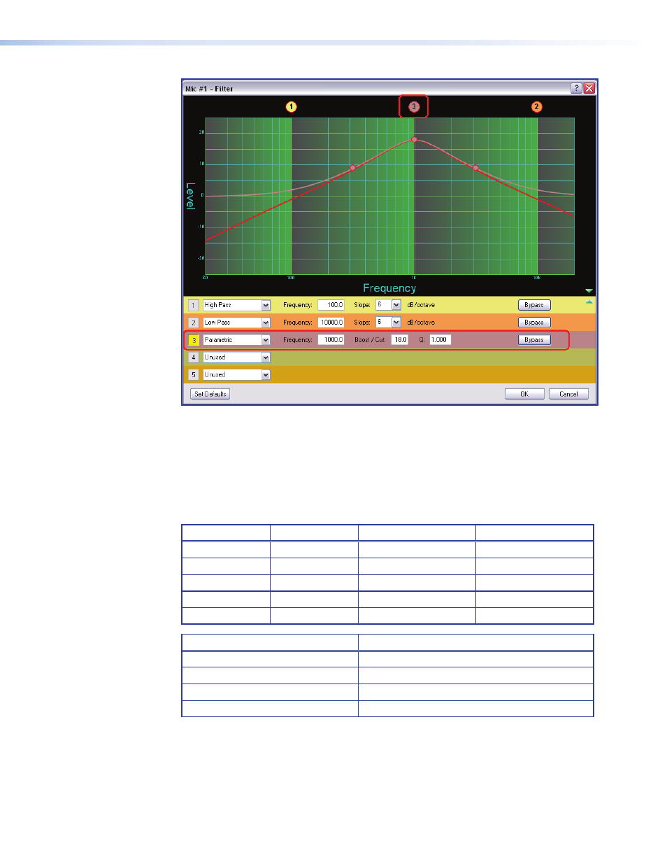
Figure 24.
Filter Dialog Box, Filter Not Bypassed
Above the graph, each filter has a "handle" (circled in red above) placed directly above
the cutoff or center frequency whose number corresponds to the filter number (outlined in
red). Click a handle or click the table row to bring focus to that filter. Click+hold+drag the
handle horizontally to change the cutoff or center frequency.
The table below shows each filter type with default parameter settings. The table
immediately following shows the possible range for each parameter.
Type
Frequency
Parameter 1
Parameter 2
High Pass
100 Hz
Slope: 6 dB
N/A
Low Pass
10000 Hz
Slope: 6 dB
N/A
Bass
100 Hz
Boost/Cut: 0.0 dB
Slope: 6 dB
Treble
8000 Hz
Boost/Cut: 0.0 dB
Slope: 6 dB
Parametric
1000 Hz
Boost/Cut: 0.0 dB
Q: 1.0
Filter Parameter
Settings Range
Frequency
20 Hz to 20 kHz
Boost/Cut
-24.0 dB to +24.0 dB
Q (Parametric EQ only)
0.707 to 15.000
Slope (HP & LP filters only)
1st Order (6 dB) and 2nd Order (12 dB)
DMP 128 • Software Control
33
- Annotator 300 (4 pages)
- Annotator and USP 507 Output Boards (2 pages)
- Annotator Setup Guide (4 pages)
- Annotator User Guide (108 pages)
- CCR-4BLB AAP (1 page)
- CCR 204 4-User (1 page)
- CIA100 (14 pages)
- CIA101 (14 pages)
- CIA112 (18 pages)
- CIA116 (18 pages)
- CTL101 (34 pages)
- DMP 64 User Guide (146 pages)
- DMP 64 Setup Guide (2 pages)
- DMP 44 LC User Guide (81 pages)
- DMP 44 LC Setup Guide (2 pages)
- DMP 128 Setup Guide (4 pages)
- DAT104 (10 pages)
- DVI-RGB 200 Setup Guide (2 pages)
- DVI-RGB 200 User Guide (19 pages)
- ECP 1000 (18 pages)
- EMOTIA Jr. 800 (2 pages)
- EMOTIA xtreme (2 pages)
- EMOTIA xtreme MX (19 pages)
- Extron TouchLink (78 pages)
- FOX USB Extender Setup Guide (2 pages)
- FOX USB Extender User Guide (19 pages)
- IPL T SFI244 (68 pages)
- IPL T SF Series Setup Guide (51 pages)
- IPL T Series Setup Guide (29 pages)
- IPL T S Series User Guide (79 pages)
- IPL T PCS4 (69 pages)
- IPL T PC1 User Guide (78 pages)
- IPL T PC1 Setup Guide (27 pages)
- IPL T CR48 (46 pages)
- IPL Pro Series User Guide PRELIMINARY (39 pages)
- IPL Pro Series Setup Guide (8 pages)
- IPI 200 Series Setup Guide (2 pages)
- IPI 100 Series Installation (2 pages)
- IPI 100 Series User Guide (86 pages)
- IPCP Pro Series User Guide (47 pages)
- IPCP Pro Series Setup Guide (10 pages)
- IPCP 505 User Guide (96 pages)
- IPCP 505 Setup Guide (6 pages)
- MGP 464 Series (146 pages)