Creating a physical dante network, Basic configuration, Star network topology – Extron Electronics DMP 128 User Guide User Manual
Page 122: Daisy chain network topology
creating a Physical Dante network
Basic configuration
A physical network is required to share Dante audio channels between DMP 128 AT
devices. Each DMP 128 AT contains a 4-port Gigabit switch with four RJ-45 connectors
located on the back panel to accept standard network cables. The 4-port switch can
operate as a standard switch described in this section or in redundant mode (see
on page 117) that switches between duplicate audio
streams during a single network failure, preventing audio stream interruption.
notE: The Dante Controller network configuration defaults to switched mode
(basic) making star and daisy-chain configurations possible. When configured
for redundant operation, different connection rules apply (see
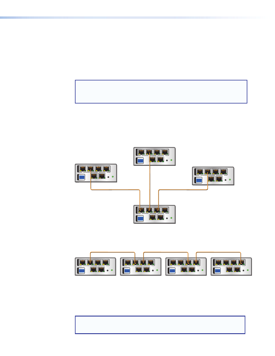
A DMP 128-based Dante network can be configured in a daisy-chain or Star network
topology using the four port switch and the Dante Controller in Switched mode.
Star network topology has one DMP 128P AT as the central unit, which is then directly
connected to up to three other units. Alternatively, a larger network switch can be used in
place of the central DMP 128 AT, allowing more than three units to be connected in the
star configuration (see figure 69).
LAN
EXP
RS-232
Tx Rx G
RESET
1
2
3
4
REMOTE
AT
DMP 128 AT #1
LAN
EXP
RS-232
Tx Rx G
RESET
1
2
3
4
REMOTE
AT
Central Unit
DMP 128 AT #4
LAN
EXP
RS-232
Tx Rx G
RESET
1
2
3
4
REMOTE
AT
DMP 128 AT #2
LAN
EXP
RS-232
Tx Rx G
RESET
1
2
3
4
REMOTE
AT
DMP 128 AT #3
Star Network Topology
Figure 69.
Star Network Topology
A daisy chain configuration can also be used. Each unit is connected to both the previous
unit and the next unit in the chain (see figure 70).
LAN
EXP
RS-232
Tx Rx G
RESET
1
2
3
4
REMOTE
AT
DMP 128 AT MASTER
LAN
EXP
RS-232
Tx Rx G
RESET
1
2
3
4
REMOTE
AT
DMP 128 AT #1
LAN
EXP
RS-232
Tx Rx G
RESET
1
2
3
4
REMOTE
AT
DMP 128 AT #3
LAN
EXP
RS-232
Tx Rx G
RESET
1
2
3
4
REMOTE
AT
DMP 128 AT #2
Daisy Chain Network Topology
Figure 70.
Daisy Chain Topology
Hybrid versions combining the star and daisy chain topologies can also be built, but a ring
topology, or any topology that creates a duplicate connection causes a connection failure
in the Dante Controller software. Redundant connections are possible using the primary
and secondary port interface structure (see
notE: Connections between DMP 128 AT ports in either a star or daisy chain
network do not need to be sequential, nor do they need to be made between the
same port numbers.
DMP 128 • Software Control
116