Rainbow Electronics DS2151Q User Manual
Page 11
DS2151Q
022697 11/46
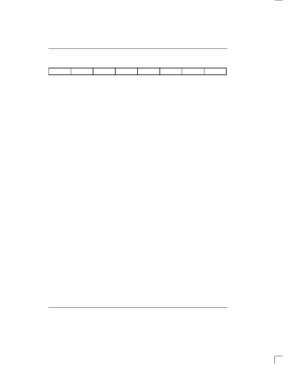
CCR1: COMMON CONTROL REGISTER 1 (Address=37 Hex)
(MSB)
(LSB)
TESE
LLB
RSAO
RLB
SCLKM
RESE
PLB
FLB
SYMBOL
POSITION
NAME AND DESCRIPTION
TESE
CCR1.7
Transmit Elastic Store Enable.
0=elastic store is bypassed
1=elastic store is enabled
LLB
CCR1.6
Local Loopback.
0=loopback disabled
1=loopback enabled
RSAO
CCR1.5
Receive Signaling All One’s.
0=allow robbed signaling bits to appear at RSER
1=force all robbed signaling bits at RSER to one
RLB
CCR1.4
Remote Loopback.
0=loopback disabled
1=loopback enabled
SCLKM
CCR1.3
SYSCLK Mode Select.
0=if SYSCLK is 1.544 MHz
1=if SYSCLK is 2.048 MHz
RESE
CCR1.2
Receive Elastic Store Enable.
0=elastic store is bypassed
1=elastic store is enabled
PLB
CCR1.1
Payload Loopback.
0=loopback disabled
1=loopback enabled
FLB
CCR1.0
Framer Loopback.
0=loopback disabled
1=loopback enabled
LOCAL LOOPBACK
When CCR1.6 is set to a one, the DS2151Q will be
forced into Local LoopBack (LLB). In this loopback,
data will continue to be transmitted as normal through
the transmit side of the SCT. Data being received at
RTIP and RRING will be replaced with the data being
transmitted. Data in this loopback will pass through the
jitter attenuator and the jitter attenuator should be pro-
grammed to be in the transmit path. LLB is primarily
used in debug and test applications. Please see the
DS2151Q Block Diagram in Section 1 for more details.
REMOTE LOOPBACK
When CCR1.4 is set to a one, the DS2151Q will be
forced into Remote LoopBack (RLB). In this loopback,
data recovered off the T1 line from the RTIP and RRING
pins will be transmitted back onto the T1 line (with any
BPVs that might have occurred intact) via the TTIP and
TRING pins. Data will continue to pass through the
receive side of the DS2151Q as it would normally and
the data at the TSER input will be ignored. Data in this
loopback will pass through the jitter attenuator. RLB is
used to place the DS2151Q into “line” loopback which is
a requirement of both ANSI T1.403 and AT&T TR62411.
Please see the DS2151Q Block Diagram in Section 1 for
more details.
PAYLOAD LOOPBACK
When CCR1.1 is set to a one, the DS2151Q will be
forced into Payload LoopBack (PLB). Normally, this
loopback is only enabled when ESF framing is being
performed. In a PLB situation, the DS2151Q will loop
the 192 bits of payload data (with BPVs corrected) from
the receive section back to the transmit section. The
FPS framing pattern, CRC6 calculation, and the FDL
bits are not looped back, they are reinserted by the