1§connection§schematic, Rf card, 1on 2 – V-Tech CAT5 System Technical Guide User Manual
Page 87: Error inuse link power, C5-f414, C5-imc
Page 87
K5 System Technical Guide
• Large Capacity: The C5-IMC can save up to 800 pieces of pictures
• Flexible time setting: When browsing the pictures on the monitor, the switching time between
different pictures can be changed on the C5-IMC
• Automatic room releasing: When the memory is full, the earliest pictures will be deleted to
make room for the new pictures .Also users can delete the pictures by themselves on the moni-
tor.
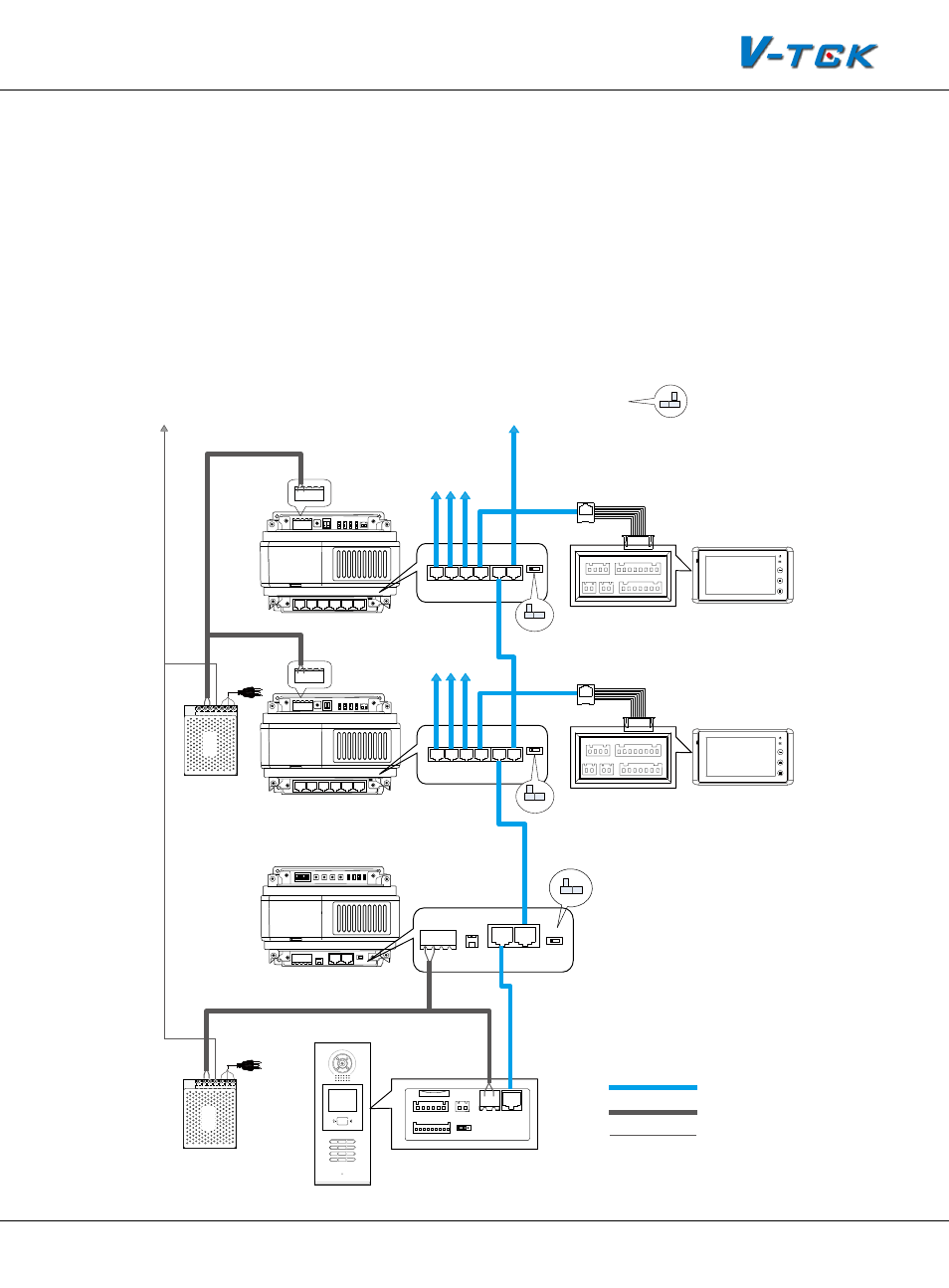
4.6.2.1§Connection§Schematic
Connect the C5-IMC as you do a distributor. And one C5-IMC can be connected to the system.
1
2
3
4
C5-AT27
PS5
1
2
3
6
5
4
7
8
9
#
0
*
RF CARD
CN1
CN2
CN-LK
J/KMB
JP-LK
Bus
EB+
EB-
N.O
LK+
LK-
+12V
1
2
3
T/R-
T/R+
P+
P+
P-
RS485
FM-SET
C5-F414
IP-MR18
AC
+
-
+
-
+
-
To other monitors
PS5
AC
+
-
1R
2W
GD
VD
T/R+ T/R-
Z1
Z2
Z3
Z4 COM COM
PR
3Y
4B
FV+ FV- P-
AU
P-
P+ P+
D1&D2
To Next C5-F414
CAT5
RVV2*1.0mm
Note that ID Code(#8001-1) setting in MR18 must be set to 0-F414
PORT-A PORT-B PORT-C PORT-D JWB(IN) JWB(OUT)
VD-SET(L=HIGH)
P- P+ P- P+
PA
S1
1
ON
2
T/R-
ERROR
INUSE
LINK
POWER
T/R+
PORT-A PORT-B PORT-C PORT-D JWB(IN) JWB(OUT)
JWB(IN)
P-
+
-
P- P+
P+
P-
VD-SET
HI / VD
HI / VD
1
2
3
4
C5-AT27
C5-F414
To other monitors
1R
2W
GD
VD
T/R+ T/R-
Z1
Z2
Z3
Z4 COM COM
PR
3Y
4B
FV+ FV- P-
AU
P-
P+ P+
D1&D2
PORT-A PORT-B PORT-C PORT-D JWB(IN) JWB(OUT)
VD-SET(L=HIGH)
P- P+ P- P+
PA
S1
1
ON
2
T/R-
ERROR
INUSE
LINK
POWER
T/R+
PORT-A PORT-B PORT-C PORT-D JWB(IN) JWB(OUT)
+
-
P- P+
P+
P-
VD-SET
HI / VD
+
-
+
-
To Next PS5
A single cable to connect
P-(Ground) together
Note that VD-SET must be set to VD if the C5-F414 is the last one of the bus
HI / VD
C5-IMC
1
ON
DIP
2 3 4 5 6
P- P+ P- P+
T/R+
FM-SET
T/R-
S201
PA201 PA202 PA203 PA204
LED201
LED202
LED203
LED204
JWB(OUT)