2§lock§connection, 1§lock§type, 2§connection§diagram – V-Tech CAT5 System Technical Guide User Manual
Page 59: 1§door§lock§controlled§with§internal§power, Page 59 k5 system technical guide, Ip-mr18 ac
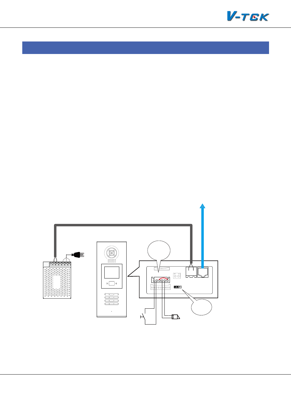
Page 59
K5 System Technical Guide
§
§ 4.2§Lock§Connection
4.2.1§Lock§Type
The door station can connect two kinds of lock:
The power-on to unlock type: The lock stays locked when there is no power, and unlocks once it
gets the power from the power supply.
The power-off to unlock type: The lock stays locked when there is power feeding it , and unlocks
once the power is cut off.
4.2.2§Connection§Diagram
The lock can get power from the door station directly or from the additional power supply, we call
these two internal power supply and external power supply separately.
4.2.2.1§Door§Lock§Controlled§with§Internal§Power
LOCK
PS5
1
2
3
6
5
4
7
8
9
#
0
*
RF CARD
CN1
CN2
CN-LK
J/KMB
JP-LK
Bus
EB+ EB-
N.O
LK+
LK-
+12V
1
2
3
T/R- T/R+
IP-MR18
AC
+
-
+ -
To C5-IPC or Distributor
LOCK
Exit Button
Set to 2-3
Connect N.O
and +12V pins
Note:
1. Electronic lock of Power-on-to-unlock type should be used.
2. Working current of lock must be less than 250mA, and working voltage must be DC12V
3. JP-LK must be set to 2-3 position, N.O. and 12V pins of CN-LK must be connected together.
4. Unlock Output(unlock mode) must be set to 0(By default)