Chapter 4 k5 system settings, C5-ipc, Rf card – V-Tech CAT5 System Technical Guide User Manual
Page 80: Lan cat5 rvv2*1.0mm
Page 80
K5 System Technical Guide
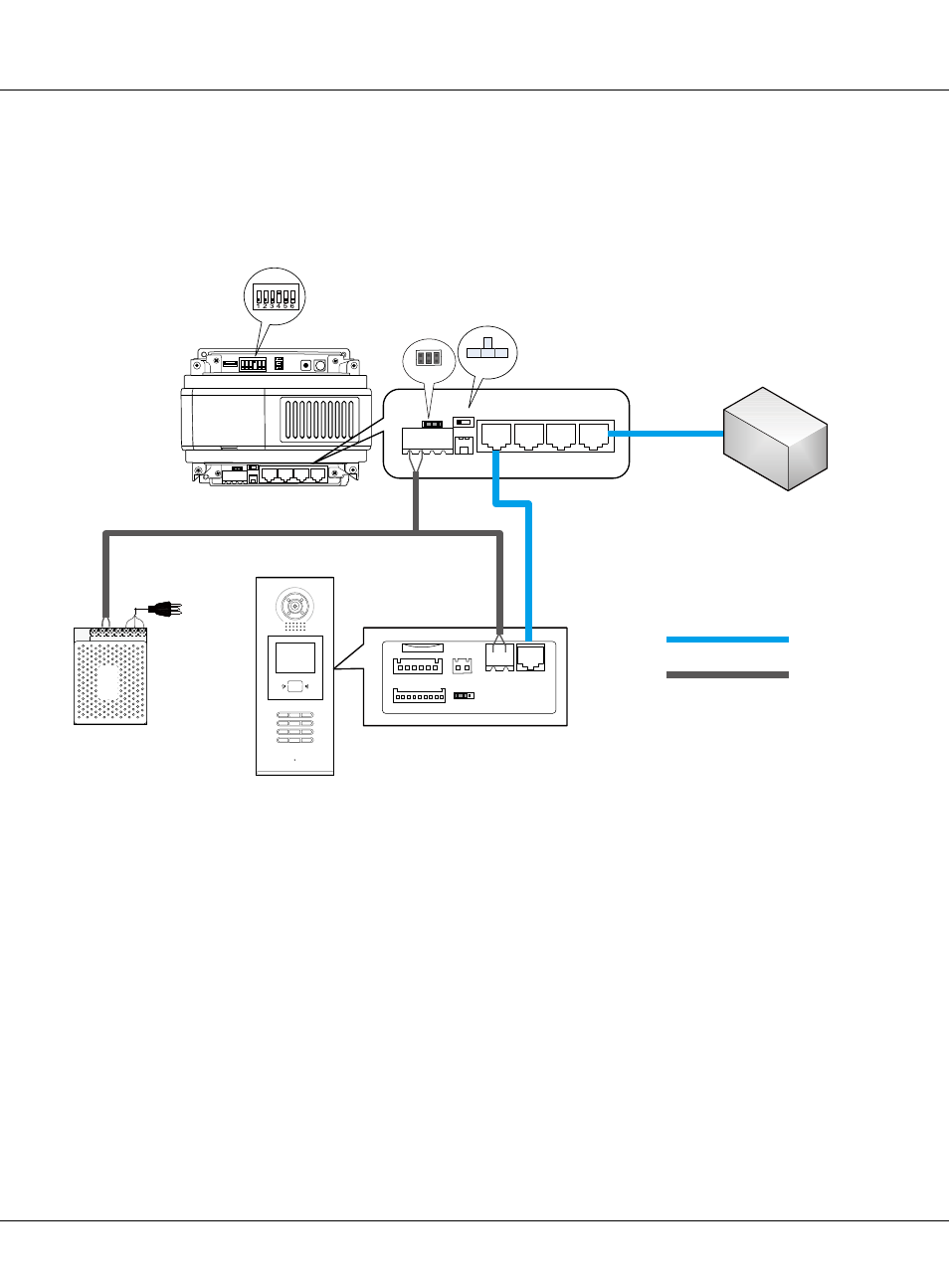
Work with Common Door Station
Door station can be set to function as common door station, being able to call all the monitors in
the network system, while unit door station can only call the monitors of its own building.
PS5
1
2
3
6
5
4
7
8
9
#
0
*
RF CARD
CN1
CN2
CN-LK
J/KMB
JP-LK
Bus
EB+
EB-
N.O
LK+
LK-
+12V
1
2
3
T/R-
T/R+
1
2
3
P+
P-
P+
P-
RS485
SW1
JWB(IN)
JWB(OUT)
CN(MDS)
ETHERNET
PA
VR600
+
S1
POWER
LINK
IN-USE
AG
1
ON
ON
DIP
DIP
2
3
4
5
6
1
2
3
P+
P-
P+
P-
RS485
SW1
JWB(OUT)
CN(MDS)
ETHERNET
C5-IPC
IP-MR18
AC
+
-
+
-
+
-
F4/F4DV/F4Q
Keep 3 jumpers
LAN
CAT5
RVV2*1.0mm
Note that ID Code(#8001-1) setting in MR18 must be set to 9
JWB(IN)
Note:
1. SW1 be set as default.
2. S1 need to be set correctly, Bit4 to ON, the rest to OFF.
3. Door station need to be connected to the JWB (IN) port of C5-IPC.
4. DS Serial NO. must be set to 9 (work as common door station).
Chapter 4 K5 System Settings