Hydraulic pipe bender – RIDGID Hydraulic Pipe Bender User Manual
Page 13
Hydraulic Pipe Bender
11
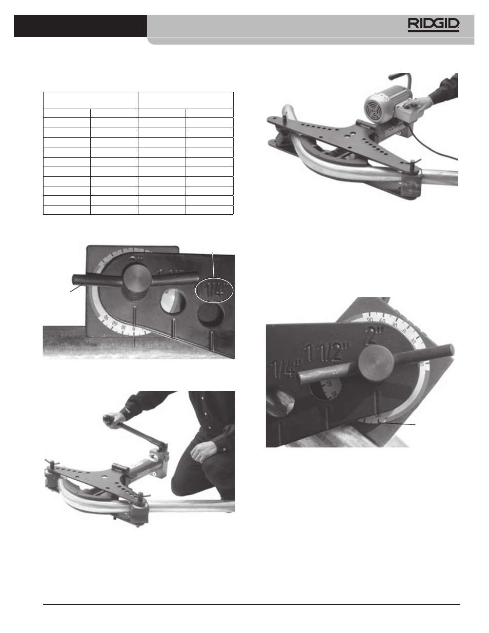
Chart 1 – Minimum Pipe Length Past The Center Of
The Pin
Figure 12 – Angle Indicator Alignment – Start of Bend
Pins Fully
Inserted
In Correct
Position
Pipe Size
Markings
Zero Alignment
Figure 13 – Operating the Manual Bender
Figure 14 – Operating the Electric Bender
3. Continue to advance the ram and bend the pipe.
As the pipe is bent, the ends will move. Stay clear
of the moving pipe. Monitor the angle indicators
(Figure 15). The average of the angles measured by
each angle indicator equals the approximate total
angle bent.
Figure 15 – Angle Indicator – End of Bend
Angle
Indicator
Watch the ram as it extends. If you can see a small
groove in the ram (Figure 16), stop advancing the
ram to prevent hydraulic leaks and ram damage.
4. For certain sizes of pipe (2
1
/
2
”, 3”), a ram extension
must be used to form a 90 degree bend. When the
groove in the ram (Figure 16) is visible, stop ad-
vancing the ram. Make sure that the pipe is prop-
erly supported to prevent it from moving or falling.
Turn the release knob to the retract position, and
retract the ram far enough to allow the extension
to be inserted between the end of the ram and the
former. Insert the extension and carefully advance
Pipe Size O.D.
Min. Distance Center Line of Pin
to End of Pipe
Inch
mm
Inch
mm
1
/
4
13,5
1.6
40
3
/
8
17,2
1.6
40
1
/
2
21,3
1.9
47
3
/
4
26,9
2.0
51
1
33,7
2.1
54
1
1
/
4
42,4
2.3
58
1
1
/
2
48,3
2.5
63
2
60,3
2.2
56
2
1
/
2
76,1
3.3
84
3
88,9
3.7
93