Machine and work area set-up – RIDGID Hydraulic Pipe Bender User Manual
Page 10
8
Hydraulic Pipe Bender
Figure 4B – Warning Label (Electric)
Electric
4. If any other equipment is being used, inspect and
maintain per its instructions to make sure it func-
tions properly.
Machine And Work Area Set-Up
WARNING
Set up the bender and work area according to these
procedures to reduce the risk of injury from electric
shock, machine tipping, crushing and other causes,
and to help prevent bender damage.
1. Locate a work area that has:
• Adequate lighting.
• No flammable liquids, vapors or dust that may
ignite. The equipment is not explosion proof and
can cause sparks.
• Clear level, stable, dry location for all of the equip-
ment and the operator.
• Properly grounded electrical outlet of proper
voltage. If in doubt, have outlet inspected by li-
censed electrician.
2. Clean the work area before setting up any equip-
ment. Wipe up any oils or liquids. Clear anything
that the pipe could hit during bending.
3. Inspect the pipe to be bent and installation area
and confirm that you have the correct tool and
formers for the job. See the Specifications Section.
Do not at tempt to bend pipe that exceeds the pipe
bender specifications. This could damage the pipe
bender.
4. Confirm that equipment to be used has been prop-
erly inspected.
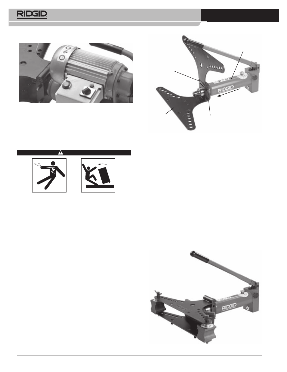
Figure 5 – Assembling 2” and 3” Benders
Hinge
Cylinder
Fully Insert
U-Bracket
Inser
t Cyli
nder
Into
The F
rame
Bending
Frame
5. Assembly
All benders should be set up on the floor or other suit-
able surface. Bender parts are heavy and awkward.
Use appropriate transport and lifting methods.
If using the accessory wheel stand or turnable tri-
pod, follow instructions for proper set-up.
• Place the bending frame with the hinged side up.
• Insert the end of the cylinder into the opening at
the end of the bending frame. Align the groove on
the cylinder with the back of the bending frame.
• Fully insert the U-bracket through the joint be-
tween the bending frame and the cylinder.
• Place the proper size corner supports for the pipe
to be bent on the lower wing over the appropri-
ate holes for the size of pipe to be bent.
• Insert the pins through the corner supports and
both wings.
Figure 6 – Assembled 2”/3” Manual Bender