Siemens SIMATIC NET PROFIBUS User Manual
Page 420
24
4 Setting Up
Version 1.0 8/00
4.4 Installation
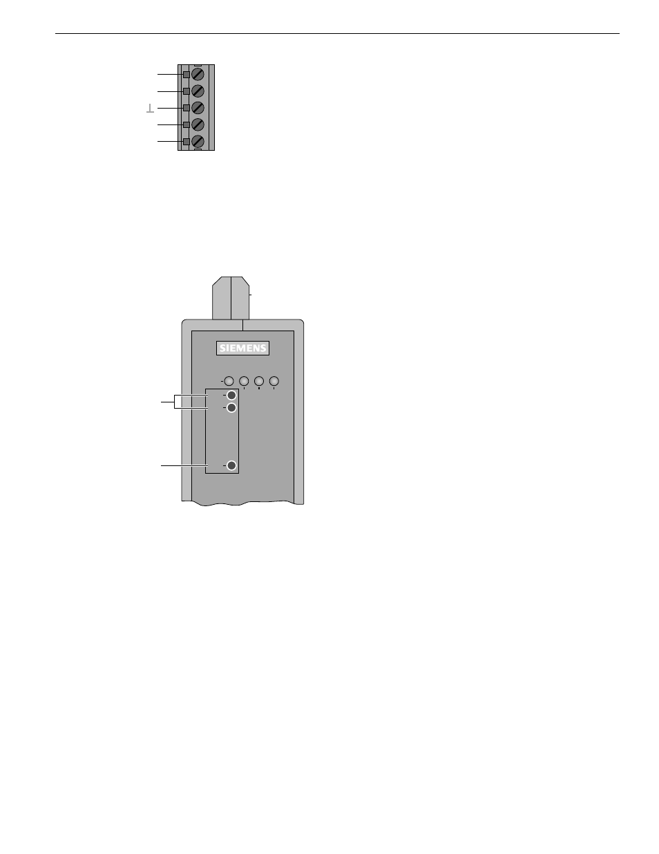
4.4.6 Defining the receiving level of the optical ports
The receiving level of the two optical Ports CH2 and CH 3
can be measured using a conventional voltmeter con-
nected to the measuring sockets. The voltmeter can be
connected and disconnected while the module is in
operation without any interference using 2 mm laboratory
test plugs.
The OLM is protected against short circuits at the measu-
ring sockets, although data transmission may be briefly
disrupted*.
With this
– the incoming optical performance can be documented,
e.g. for later measurements (ageing, damage)
– a good/poor check can be carried out (limit value).
Further information can be found in Appendix 8.4
”Measuring sockets“ p.35.
* Only an ungrounded, high-resistance voltmeter may be
used to take measurements.
The reference potential socket may not be connected to
the OLM housing.
CH 1
System
PROFIBUS OLM
CH 2
CH 3
GND
Receive
Signal
Intensity
CH 2 CH 3
Measuring sockets
Reference potential
Fig. 12: Signaling contact – pin assignment 5-pin terminal block
ᮣ
Pin assignment, 5-pin terminal block:
terminals F1 and F2.
ᮣ
Always ensure that the pins are correctly assigned at
the 5-pin terminal block. Make sure that the connecting
leads of the signaling contacts are adequately insula-
ted, particularly if you are working with voltages greater
than 32 V. Incorrect assignment can lead to destruction
of the module.
L1+ / +24 V
F1
M /
F2
L2+ / +24 V*
Fig. 13: Location of the measuring sockets