3 redundant optical ring, 2 star topology 13 3 network topologies – Siemens SIMATIC NET PROFIBUS User Manual
Page 409
3.2 Star topology
13
3 Network Topologies
Version 1.0 8/00
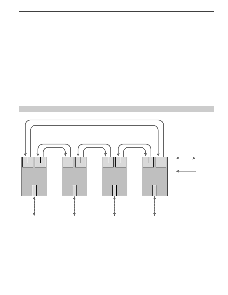
Fig. 4: Network structure in a redundant optical ring topology
RS 485 bus line
Optical fiber
Terminal unit /
bus segment
OLM/P12
OLM/G12 (-1300)
CH 1
CH 3
T
R
CH 2
T
R
Terminal unit /
bus segment
OLM/P12
OLM/G12 (-1300)
CH 1
CH 3
T
R
CH 2
T
R
Terminal unit /
bus segment
OLM/P12
OLM/G12 (-1300)
CH 1
CH 3
T
R
CH 2
T
R
Terminal unit /
bus segment
OLM/P12
OLM/G12 (-1300)
CH 1
CH 3
T
R
CH 2
T
R
3.3 Redundant optical ring
Ⅲ
Switch on the terminating resistors in the bus port connectors (see 4.4.3, ”Connecting the electric RS 485 bus
lines“, p. 22) at both ends of the electrical star segment.
Ⅲ
Do not connect a bus subscriber to the electrical star segment wherever possible.
Modules with one or two optical ports can be used to create an active PROFIBUS star coupler. Modules with one
optical port are sufficient for connecting a terminal or an RS 485 bus segment to the active star coupler.
If the link monitoring on the optical ports is activated, the fiber optic links are monitored by the respectively connected
OLM.
Note:
Optical ports which are not assigned (for instance, because they are reserved for a future system extension) indicate
a fiber break if the link monitoring is activated.
You can prevent this error report from being issued by activating the operating mode ”Line without fiber link monito-
ring “ at the non-assigned ports.
Please note that optical ports which are not connected must always be fitted with protective caps to guard against
extraneous light and dirt.