2 star topology, 12 3 network topologies – Siemens SIMATIC NET PROFIBUS User Manual
Page 408
12
3 Network Topologies
Version 1.0 8/00
3.2 Star topology
3.2 Star topology
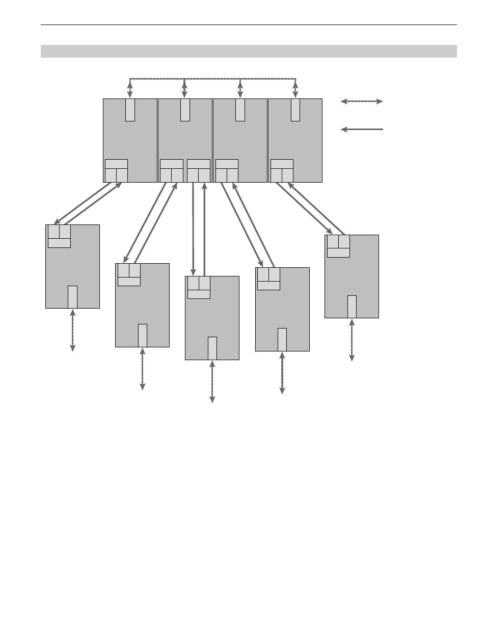
Fig. 3: Network structure in an optic star topology
Terminal unit /
bus segment
Terminal unit /
bus segment
Terminal unit /
bus segment
Terminal unit /
bus segment
Terminal unit /
bus segment
CH 2
T
R
OLM/P11
CH 1
CH 2
T
R
OLM/P11
CH 1
CH 2
T
R
CH 3
T
R
OLM/G12
CH 1
CH 2
T
R
OLM/G11-1300
CH 1
OLM/P11
CH 2
T
R
CH 1
OLM/G11-1300
CH 2
T
R
CH 1
OLM/P11
CH 2
T
R
CH 1
OLM/G11
CH 2
T
R
CH 1
OLM/G11
CH 2
T
R
CH 1
Electrical star segment
S0 = 1
S0 = 1
S0 = 1
S0 = 1
RS 485 bus line
Optical fiber
Several modules are combined to form an active PROFIBUS star coupler. Other modules are connected to this by
dual-fiber optical fiber lines. The modules of the star coupler are connected to one another via the electrical port
(electrical star segment).
All OLM types for different fiber types (plastic, PCF, glass) can be combined using the electrical star segment.
Please note:
Ⅲ
CH1 in mode ”Monitor off“ (S0 = 1) must be activated on all OLMs which are connected to the electrical star
segment. This deactivates the segmenting function of the RS 485 port on these OLMs, providing a high degree
of availability of the electrical star segment.
Ⅲ
Ensure that the electrical star segment is wired carefully. Keep it as small as possible to avoid interference
injection into the electrical star segment, and from here into the entire network. This can be achieved by laying
out the OLMs in the electrical star segment directly next to each other on a hat rail.