1 unbuffered pwm signal generation, Unbuffered pwm signal generation, Pwm period and pulse width – Freescale Semiconductor MC68HC08KH12 User Manual
Page 168
Advance Information
MC68HC(7)08KH12
—
Rev. 1.1
168
Freescale Semiconductor
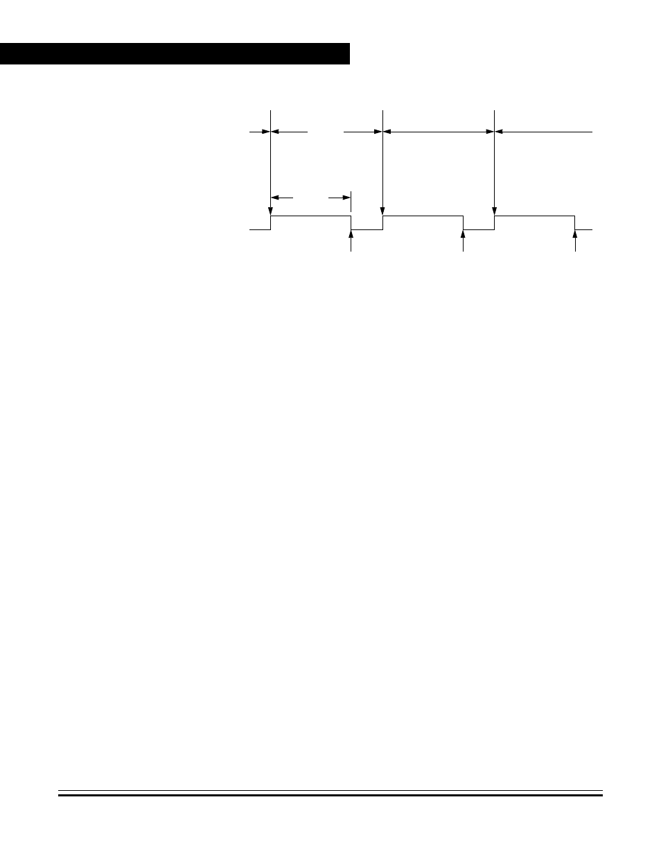
Figure 11-2. PWM Period and Pulse Width
The value in the TIM counter modulo registers and the selected
prescaler output determines the frequency of the PWM output. The
frequency of an 8-bit PWM signal is variable in 256 increments. Writing
$00FF (255) to the TIM counter modulo registers produces a PWM
period of 256 times the internal bus clock period if the prescaler select
value is 000
(see 11.9.1 TIM Status and Control Register (TSC)
The value in the TIM channel registers determines the pulse width of the
PWM output. The pulse width of an 8-bit PWM signal is variable in 256
increments. Writing $0080 (128) to the TIM channel registers produces
a duty cycle of 128/256 or 50%.
11.4.4.1 Unbuffered PWM Signal Generation
Any output compare channel can generate unbuffered PWM pulses as
described in
11.4.4 Pulse Width Modulation (PWM)
unbuffered because changing the pulse width requires writing the new
pulse width value over the old value currently in the TIM channel
registers.
An unsynchronized write to the TIM channel registers to change a pulse
width value could cause incorrect operation for up to two PWM periods.
For example, writing a new value before the counter reaches the old
value but after the counter reaches the new value prevents any compare
during that PWM period. Also, using a TIM overflow interrupt routine to
PTEx/TCHxA
PERIOD
PULSE
WIDTH
OVERFLOW
OVERFLOW
OVERFLOW
OUTPUT
COMPARE
OUTPUT
COMPARE
OUTPUT
COMPARE