FUJITSU MB86617A User Manual
Page 122
LSI S pecification
MB86617A
Rev.1.0
Fujitsu VLSI
117
<
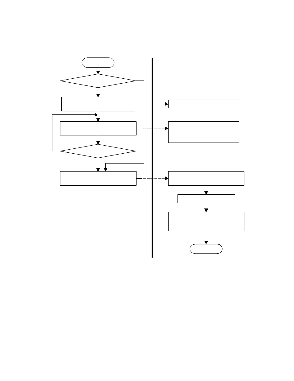
< Flow chart after bus reset completion
Figure 11.2.1.2 Flow example for Self-ID packet receiving after bus reset completed
Note1: When Asyn-FIFO sel (mode-control register[3]) is 1 and send/rec (mode-control register [2]) is 1, Asynchronous receive
FIFO (256 byte) and Bridge FIFO (2048 byte) are used with combined as Asynchronous receive buffer.
In other case, Asynchronous receive FIFO (256 byte) and Asynchronous transmit FIFO (256 byte) are used with
combined.
Note2: When Asyn-FIFO sel is 1 and transmit/rec is 1, Asynchronous transmitting FIFO (256 byte) and Bridge FIFO (2048 byt)
are cleared,
When Asyn-FIFO SEL is 1 and transmit/rec is 0, Asynchronous receiving FIFO (256 byte) and Asynchronous
transmitting FIFO (256 byte) are cleared. Asynchronous transmit FIFO and Bridge FIFO are combined to be set in
Asynchronous transmit buffer. Set Asynchronous receive FIFO to Asynchronous receive buffer.
When Asyn-FIFO sel is 0, Asynchronous receive FIFO (256 byte) and Asynchronous transmit FIFO (256 byte) are cleared
and re-set Asynchronous receive FIFO to Asynchronous receive buffer, Asynchronous transmit FIFO to Asynchronous
transmit buffer.
START
Issue Asynchronous receive (03h)
instruction.
Read one word from receive
Asynchronous data port.
END
data req bit
Read one word of the received data
and increment the read pointer of
buffer.
recv busy bit=0
Issue Remove busy (04h) instruction.
Prepare for reading received data.
Receive Remove busy(04h) instruction.
Clear the receive Asynchronous buffer
and set FIFO according to FIFO mode.
(Note 2)
‘1’
Read Self-ID?
Yes
No
‘0’