1 connection blade stacking, Connection blade stacking, Connection blade stacking" on – FUJITSU PRIMERGY BX400 S1 User Manual
Page 98: 98 operating manual, Hot-plug components, Bx400 s1, Figure 26: cx4 cable
98
Operating Manual
BX400
S1
Hot-plug components
©
c
o
gni
ta
s.
Ge
se
lls
ch
ft f
ür T
ec
hn
ik
-Do
ku
m
ent
at
io
n
m
b
H 20
12
P
fa
d:
C
:\P
rogr
am
m
e
\F
CT
\t
im
_ap
p\
tim
_l
oc
al
\w
ork
\W
A
LT
E
R
\O
B
J_
DO
K
U
-9
24
9-0
04
.fm
8.2.2.1
Connection blade stacking
Up to 4 Connection Blades GbE Switch/IBP 36/8+2 can be operated together
to form a so-called stack. One of the connection blades takes on the role of the
master. This connection blade is used to administer all modules of the stack. All
modules of a stack act as one connection blade. In this way, connection blade
stacking offers a large number of ports with minimum administrative effort.
The connections within a stack are established through the stacking ports of the
connection blades. The internal stacking ports to the midplane of the system
unit are each used to connect two connection blades that are installed in the
same fabric, i.e. in two adjacent slots. Connection blades in different fabrics are
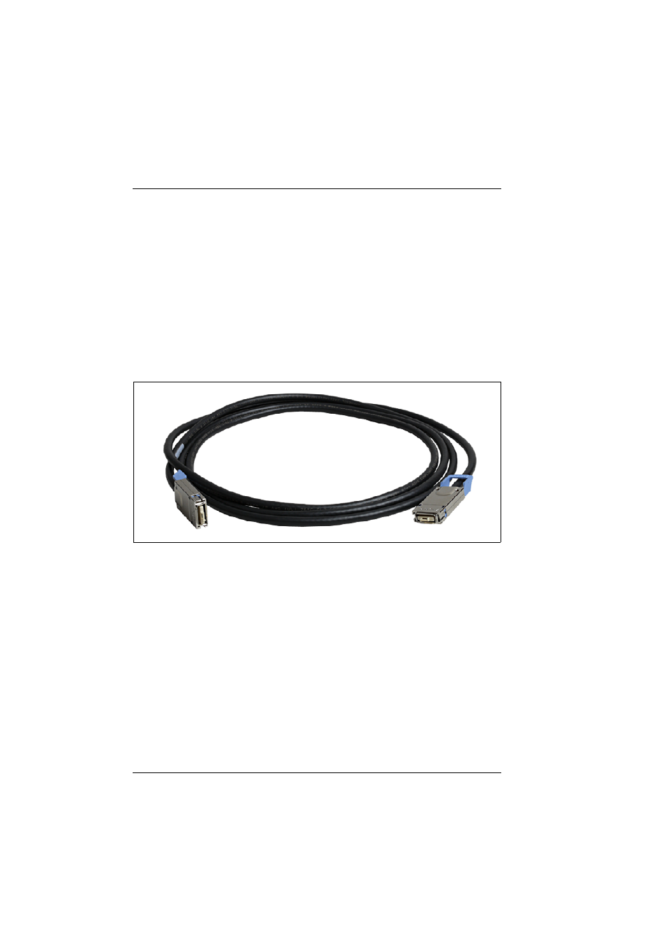
connected through the external ports using CX4 cables.
Figure 26: CX4 cable
The stacking connections within a stack must form a circuit. Connection blade
stacks can be formed within a system unit, across several system units of a rack
or across several system units in different racks.
Further information
You determine which connection blade takes on the master role through the
sequence and the intervals at which the connection blades are booted and
connected with each other. For more detailed information and additional
possible configurations, see the manuals "PRIMERGY BX900 Blade Server
Systems – Ethernet Connection Blade Module IBP Version – User’s Guide",
"PRIMERGY BX900 Blade Server Systems – Ethernet Connection Blade
Module Switch Version – User’s Guide" and " ス イ ッ チ ブ レー ド (10Gbps 18/8)
取扱説明書
" (for the Japanese market).