Rear panel descriptions, Figure 21 . connectors on the controller’s rear p, Cy berlight lcd controller – High End Systems High End LCD Controller for Studio Color User Manual
Page 36
2-2
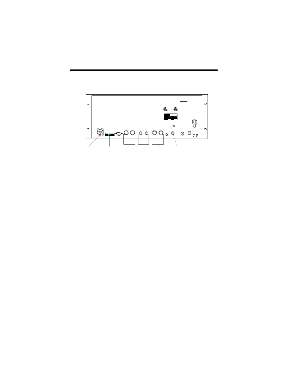
Rear Panel Descriptions
Studio Color LCD Controller
Rear Panel Descriptions
Figure 2-1 shows the locations of the connectors on the rear
panel of the Studio Color LCD controller.
Figure 2-1. Connectors on the controller’s rear
panel.
Data Link Out port: An XLR female jack that sends
control data to all connected fixtures. For more information,
see the section titled “Connecting Fixtures” on page 2-9.
Personality switches: The four switches in switch block A
are reserved for future use. The eight switches in switch
block B define the controller’s modes of operation. For more
information, see the section titled “Setting the Switches” on
page 2-4.
Serial communication port: Standard PC AT
®
style 9-pin
serial communications port conforming to the RS-232C (also
known as EIA-232-D) standard. This port is used for
playback control using Lightwave Control Center (LCC)
software, or for backing up/restoring memories and pages
using a personal computer. The port operates at 9600 baud, 8
data bits, no parity, and 1 stop bit. For more information, see
the section titled “Other Connectors” on page 2-23.
DATA LINK
OUT
CAUTION
WARNING
PERSONALITY
SLAVE
MASTER
RS-232
SERIAL PORT
1-6
ANALOG INPUTS
7-12
REMOTE
ENABLE
FUSE
CAUTI ON
voltage
select
1 2 3 4
A
B
M I DI
IN
OUT
STEREO
AUDIO
INPUT
11
5
T o reduce t he r isk of f ir e or
electr ic shock, do not expose
this device to rain or m ois ture.
L
R
IMPORTANT SAFETY INFORMATION. SEE INSTRUCTION MANUAL BEFORE USE.
WICHTIGE SICHERHEITSINFORMATIONEN. BEDIENUNGSANLEITUNG VOR GEBRAUCH LESEN!
D'IMPORTANTE CONSIGNE DE SÉCURITÉ. VOYEZ LE MANUEL D'INSTRUCTION AVANT L'UTILISATION DE L'APPAREIL.
This device compli es with part 15 of the FCC rules.
Operation is subject to the f ollowing two conditions:
(1) This device may not cause harmful int erferences,
and (2) this device mus t accept any interference
that may c ause undesi red operation.
To prevent electric shock, do
not remove cover. No user
serviceable parts inside.Refer
servicing to qualified service
personnel. Replace fuse with
same type and rating.
R AT IN G IN FO R MAT IO N
V OL T AG E : 11 5V A C/ 23 0V A C
C U R R EN T : 0. 25A/ 0. 15 A
F R E Q UE N C Y : 50 -6 0 H Z
115 V 0.5 A, SLOW BLOW
230 V 0.315 A, SLOW BLOW
1 2 3 4
1 2 3 4 5 6 7 8
1 2 3 4 5 6 7 8
Data Link Out
port
Personality
switches
Serial
communication
port
MIDI In/Out
ports
Master/Slave
ports
Analog inputs
Remote Enable
port
Stereo Audio
input
MODEL
SERIAL
DATE
QC
VOLTAGE
HZ
230
15FM123456
Cy berlight LCD Controller
50
80
59
000
1
ETL Listed
C onforms to
U L Std. 1950
C ertified to
C AN /CSA C 22.2 No. 950
67501
R
C
R
LIGHTWAVE RESEARCH
2217 West Braker Lane
Austin, Texas U.S.A.