System, Ux bus (p. 148) and edit the func, Menu list – Roland VR-120HD Direct Streaming AV Mixer User Manual
Page 148

148
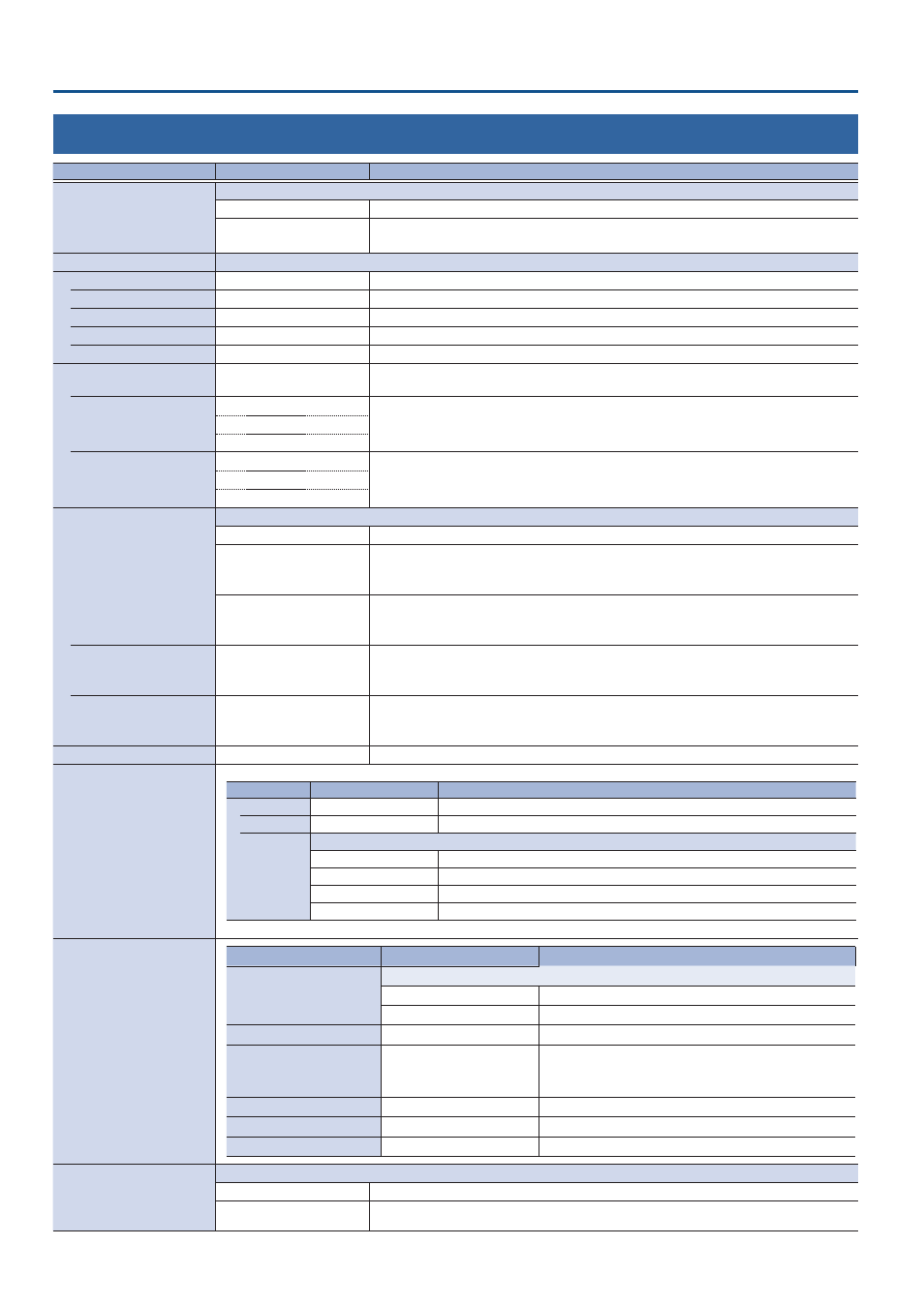
Menu List
26: System
Menu item
Value
(bold text: default value)
Explanation
HDCP
Specifies whether HDCP is enabled (ON) or disabled (OFF).
OFF
Copy-protected (HDCP) video cannot be input.
ON
Copy-protected (HDCP) video can be input. HDCP is also added to the video that is output.
* Video/audio from the SDI OUT connectors and the USB STREAM port are not outputted.
Output Format
Specifies the output format.
System Format
(*16)
1080p
, 720p
Specifies the system format.
HDMI Out 1–3
1080p
, 1080i, 720p
Sets the output format for the HDMI OUT 1–3 connectors.
SDI Out 1–3
1080p
, 1080i, 720p
Sets the output format for the SDI OUT 1–3 connectors.
USB Out
1080p
, 720p
Specifies the output format of the USB STREAM port.
Stream/Record
1080p
, 720p
Specifies the output format of the DIRECT STREAM port.
Frame Rate
(*16)
60,
59 .94
, 50, 30, 29.97, 25,
24, 23.98Hz
Specifies the frame rate.
USB Out
(*16)
30, 60Hz
Specifies the frame rate of the USB STREAM port.
* The value differs depending on the “Frame Rate” setting.
29.97,
59 .94Hz
25, 50Hz
Stream/Record
(*16)
30, 60Hz
Specifies the frame rate of the DIRECT STREAM port.
* The value differs depending on the “Frame Rate” setting.
29.97,
59 .94Hz
25, 50Hz
Reference
Specifies the reference clock of the VR-120HD.
Internal
The VR-120HD’s internal clock is used as the reference clock
External
A synchronizing signal input via the REFERENCE IN connector is used as the reference clock.
Black-burst (frame synchronization), bi-level, and tri-level synchronizing signals are
supported.
SDI 1–6
A signal input via one of the SDI IN 1–6 connectors is used as the reference clock.
The VSYNC (vertical synchronizing) signal output from the VR-120HD is synchronized to the
VSYNC signal input via SDI.
Clock Adjust
-1920–
0
–1920
This adjusts the phase horizontally.
Adjust this when output is horizontally out of sync with the operation of other devices using
the same clock.
Line Adjust
-1200–
0
–1200
This adjusts the phase vertically.
Adjust this when output is vertically out of sync with or field-shifted from the operation of
other devices using the same clock.
Lock Status
––
Indicate the lock status.
Bluetooth Pairing
Menu item
Value
Explanation
Bluetooth
OFF
, ON
Turns the Bluetooth function on/off.
Pairing
Exec
Begins pairing with a Bluetooth device.
Status
Displays the Bluetooth connection status.
Off
Bluetooth off
Pairing Mode
Now pairing
Not Connected
Waiting for connection
Connected
Connected
Date&Time
Menu item
Value
Explanation
Configure
Selects how the time is set.
Manual
The time is set manually.
Using NTP
The time is set by retrieving the time from an NTP server.
Time Zone
–
Sets the time zone.
Date Format
Month/Day/Year
Day/Month/Year
Year/Month/Day
Sets the format used for displaying the date.
Clock Display Type
Analog
, Digital
Sets the type of time display used.
NTP Server
–
Specifies the default NTP server.
Manual
Enter
The time is set manually.
Panel Operation
Specifies the operation mode for video transitions.
Dissolve
This mode selects the video to output and immediately outputs it to the PGM bus.
PGM/PST
In this mode, the PST video is displayed in the PVW bus, and you can check the video before outputting it
to the PGM bus.
(*16) A change in the setting is not applied until you press the [VALUE] knob to confirm.
