PLANET WNAP-1110 User Manual
Page 37
User’s Manual of WNAP-1110
-37-
Step 2. Configure the SSID and its corresponding VLAN ID. The detailed parameters are shown as the figure
above.
Step 3. STA1, STA2, STA3 and STA4 join to the wireless network with SSID1, SSID2, SSID3 and SSID4,
respectively.
Step 4. Click Save to apply the current security settings for the selected SSID.
1. The wireless STAs, joined to the network with different VLAN IDs, cannot communicate with
each other, for example, STA1 and STA2.
2. The wireless STAs, joined to the network with the same VLAN ID, can communicate with
each other, for example, STA1 and STA3.
3. All wireless STAs can log on to the Web management page of the WNAP-1110 and manage
the access point, for example, STA1, STA2, STA3 and STA4.
4. All the packets received in the wired network from the wireless STA will be added a
corresponding VLAN Tag of the wireless STA, unless the VLAN ID of the wireless network is
set to 1.
2. Configuring the Switch
Step 1. Enable 802.1Q Tag VLAN function on the switch.
Step 2. Make sure the Untag frames are forwarded.
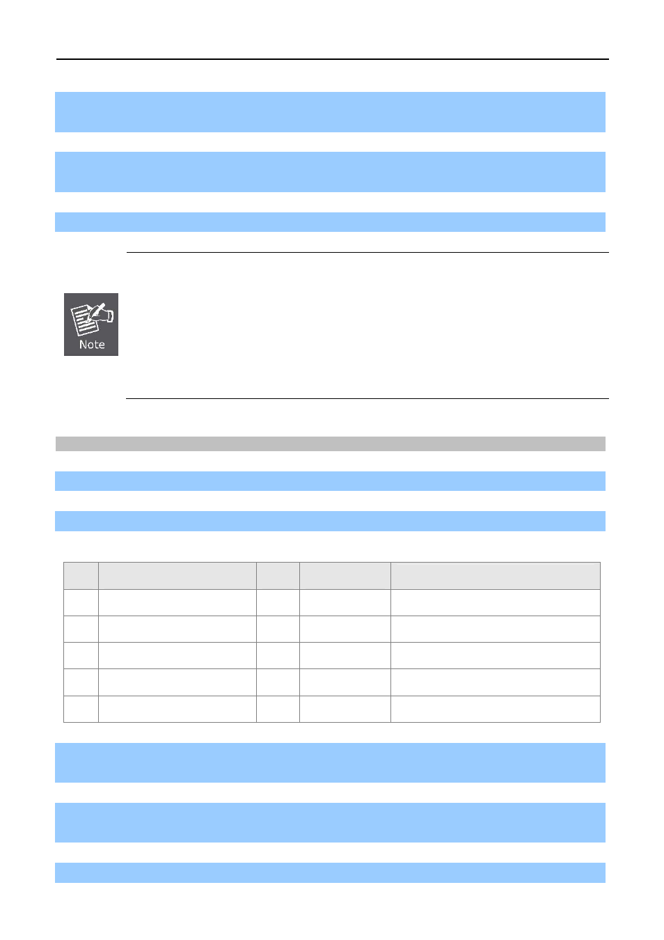
The following table shows the detailed configuration of the switch
Port
VLAN ID
PVID
Egress Rule
Processing mode of Untag Frames
1 1
1 Untag
Forwarding
2 2
2 Untag
Forwarding
3 3
3 Untag
Forwarding
4 4
4 Untag
Forwarding
5
Port 5 belongs to all VLANs
1
Tag
Forwarding
Step 3. Connect PC1, PC2, PC3 and PC4 to port1, port2, port3 and port4 of the switch, respectively. The
corresponding VLAN IDs of the four ports are 1, 2, 3 and 4.
Step 4. Configure port5 of the switch to be the member of VLAN1, VLAN2, VLAN3 and VLAN4 and connect it
to the LAN port of the WNAP-1110.
Step 5. Configure the VLAN ID of the PC that can log on to the Web management page of the WNAP-1110 via