Conditions for cabinet construction design – Yaskawa i80M Connecting Manual User Manual
Page 8
4
CONDITIONS FOR CABINET CONSTRUCTION DESIGN
Take the following into consideration when cabinets and pendants used to contain the CPU
module and other units are designed.
4.1
MOUNTING CONDITIONS
(1) Make sure that the cabinets are of a totally-enclosed type. (For details, see Par. 4.4. )
(2) Design the cabinet so that the difference between the average inner-air temperature and
ambient temperature is less than 10”C. (For details, see Par. 4.2. )
(3) Install a fan inside totally-enclosed cabinets to improve the internal cooling efficiency and
to prevent localized temperature increases by circulating air inside the cabinets. (Rule of
thumb is: The velocity of the circulating air should be greater than 2m/s on the surfaces of
the printed circuit boards of the units) Forced air should not blow directly on the printed cir-
cuit boards.
(4) Seal the cable openings, doors, etc. completely.
(5) Since the CRT display on the CRT panel deflects due to magnetic influences and collects
air borne dust due to high-voltage operation, special precaution is required. (For details, see
Pars. 4.4 and 4.5. )
(6) The units that are exposed to the cabinet surfaces are dust-proof. However, do not install
them in locations
cutting fluid and cuttings may directly splash on them.
Mount the units so as to allow easy checking, removal and reinstalling during maintenance
work.
(8) For mounting the servo unit, see Section 5.
(9) For mounting the spindle drive unit, read the instruction manual of the spindle drive unit.
(10) Precautions for Mounting CPU Module
Observe particularly the following points when mounting the CPU module.
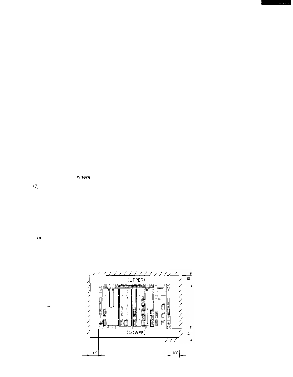
Mount the unit in the direction shown in the figure below.
(b) Provide space of more than 100 mm in the upper section and 100 mm in the lower section
of the unit for better ventilation and easier maintenance.
Also provide space of more than
100 mm in both right and left sections of the unit for easier replacement of the battery.
/ / / / / / / / / / / / / / / / /
Fig. 4.1 Mounting Space