Yaskawa i80M Connecting Manual User Manual
Page 27
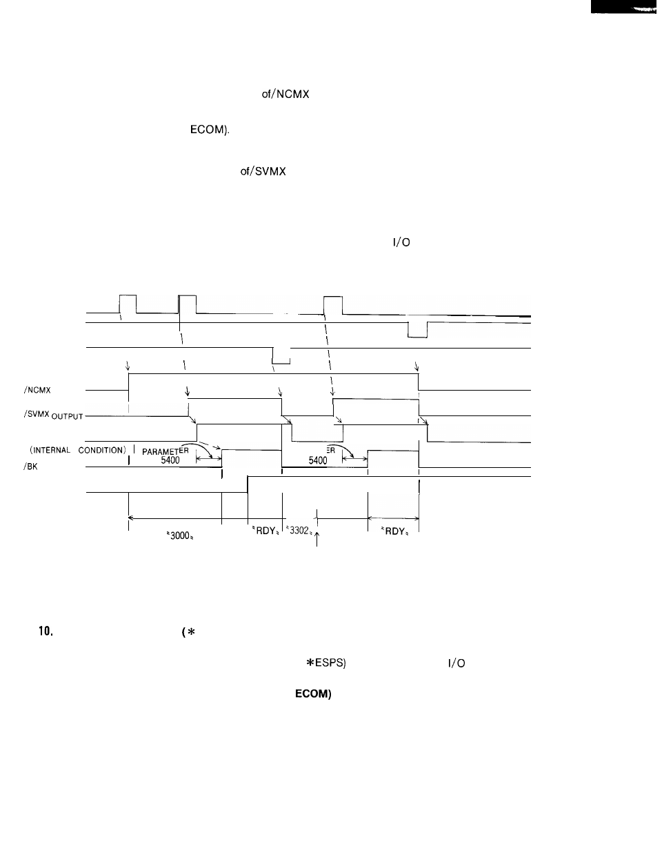
With an external servo unit, design the the servo control circuit power input sequence so
that the circuit is energized at the output
signals.
(c) Again make the same power switching (depressing the POWER ON button or closing the
circuit between EON and
Now, the servo power supply is turned on, and the out-
put of/SVMX signals (servo power input and output) is activated.
With an external servo unit, design the servo power circuit power input sequence so that
the circuit is energized at the output
signals.
(d) /BK output is turned on by parameters after the servo is ready (in servo clamp condi-
tion). Release the brake unit with this signal.
(e) When the external circuit is ready after the circuit between/SVMX is closed, and the con-
trol becomes ready, close the MRD (machine ready) input of the
module. Then, RDY
is displayed on the CRT, and operation becomes possible.
POWER ON PB
OR EON INPUT
POWER OFF PB
ON EOF INPUT
\
\
* ESP INPUT
\
\
\
I
\
\
\
OUTPUT
I
I
SERVO READY
I
PARAMETER
OUTPUT
pm
pm
I
MRD INPUT
I
I
I
I
ALARM CODE
’2190>
‘3000.
:
RESET KEY
ON
Fig. 10.4 Time Chart of Power Supply Turning on Sequence
3.2 EMERGENCY STOP
ESP) INPUT
When the emergency stop input circuit (* ESP) is open, the control stops totally, the /SVMX and
/BK are turned off, and the emergency stop output (
of general purpose
module is
opened.
10.3.3 EXTERNAL POWER ON- OFF (EON, EOF,
INPUT
The control can be switched on and off by external input signals, in the same way as the de-
pressing of the POWER ON/OFF buttons on the NC operator’s station. When the circuit be-
tween EON and ECOM is closed, the logic circuit or servo power of the control is energized.
When the circuit between EOF and ECOM is opened, the logic circuit or servo power of the
control is deenergized.
2 7