Yaskawa i80M Connecting Manual User Manual
Page 265

21. 3.2.3 OPTIONAL STOP INPUT (OPT #30406)
This input invalidates the MO1 command.
While the optional stop input is closed, the MO1 command is ignored.
21. 3.2.4 END-OF-PROGRAM INPUT (EOP # 30410), REWIND INPUT (RWD # 3041 1), AND
REWIND STATE OUTPUT
# 35376)
(1) End-of-program
and Rewind
Inputs
These inputs determine the procedure that the control performs at the end of M02/M30 com-
mand execution.
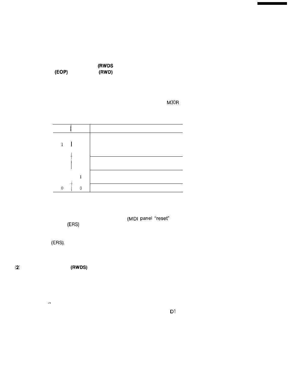
The control takes the actions indicated in Table 21. 14 depending on the EOP and RWD input
states prevailing when the completion input (FIN) relative to the M02/M30 command closes.
In general, the M02R output is connected to the EOP input, and the
is connected to the
RWD input.
Table 21.14 Relationship between the EOP/RWD Inputs and
Actions to Be Taken
EOP RWD
1
1
0
0
I
Actions to be taken
The control goes into standby mode after re-
winding part programs and resetting programs,
The control goes into standby mode after re-
setting programs,
The control goes into standby mode after re-
setting programs.
The control goes into standby mode after re-
winding part programs.
The control goes into standby mode,
1: Closed. O : open
NOTE
1. The above EOP/RWD function is the same as the program reset
function except that the reset procedure
key ON or
external reset
input closure) and NC memory rewinding procedure
are not performed.
For the details of the reset procedure, see under EXTERNAL RESET
INPUT
2. While the program reset function is being executed, the circuit be-
tween reset state outputs RST1 and RST2 is closed for one second.
Rewind State Output
This output indicates that the control is rewinding a part program.
While the RWD input is rewinding a part program in response to the M02/M30 command, the
RWDS output is generated.
NOTE
When using this input, set parameter RWDOUT (pm5000
) to 1. The
output is not generated if the parameter is set to O.
265
