Yaskawa i80M Connecting Manual User Manual
Page 271

21. 3.3 SERVO AXIS CONTROL l/O
21. 3.3.1 MANUAL HANDLE AXIS SELECTION
(1) Manual Handle Feed Axis Selection Inputs (HI # 30700-H8 # 30707)
When a manual pulse generator is provided, these inputs designate axis movement by the
manual pulse generator.
When one of these signal inputs is closed with the manual handle
generator moves the associated axis. If two or more input signals
does not take place.
selected, the manual pulse
are closed, axis movement
(2)
Manual 3-axis Simultaneous Handle Feed Axis Selection Inputs
#
30800-2H8 # 30807,
3H1
# 30817)
When this input signal is closed with a manual 3-axis simultaneous pulse generator provided, up
to
3
axes can be moved.
First handle axis selection (HI
Second handle axis selection
Third handle axis selection (3H1
NOTE: Each handle axis selection signal is effective for only one axis.
21. 3.3.2 MANUAL FEED AXIS DIRECTION SELECTION INPUTS ( + 1 # 30710 TO + 8
# 30717, -1 # 30720 TO -8 #30727)
When the control is in the manual jog, rapid traverse, or manual step feed mode, these inputs
are used to specify the axis to be moved and the direction of movement.
When the plus or minus direction input of a specific axis is closed, axis movement takes
place. When all axes are designated, all of them can be moved simultaneously.
NOTE
If both the plus and minus direction inputs of a selected axis are closed
or open, that axis does not move.
If such a condition occurs during axis
movement, the axis decelerates to a stop.
21. 3.3.3 OVERTRAVEL INPUTS
# 30740
# 30747,
●
–OT1 # 30750
# 30757)
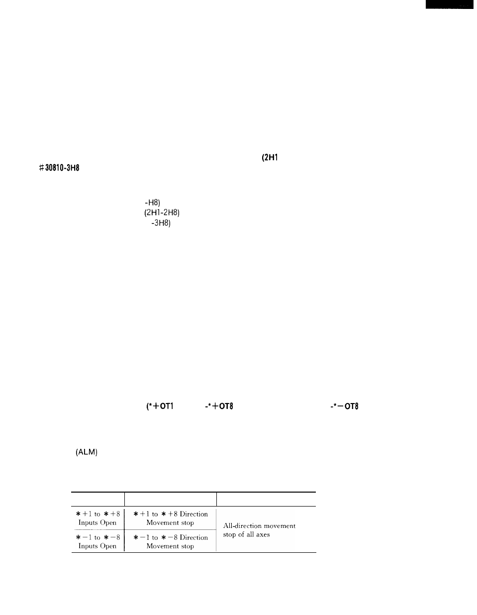
These inputs are used to indicate that the movable mechanisms have reached the stroke end,
When an overtravel input is opened, the associated axis stops as indicated in Table 21. 19
and the alarm
output closes to display an alarm on the CRT screen.
Table 21.19 Movement Stop Direction when Overtravel Input is Open
. .
Manual operation mode
Automatic operation mode
271
