7 sealing and closing the sunny island – SMA SI 3.0-11 Installation User Manual
Page 61
SMA Solar Technology AG
7 Electrical Connection
Installation Manual
SI30M-44M-60H-80H-IA-en-30
61
Checking the wiring of the communication products
Checking the system devices
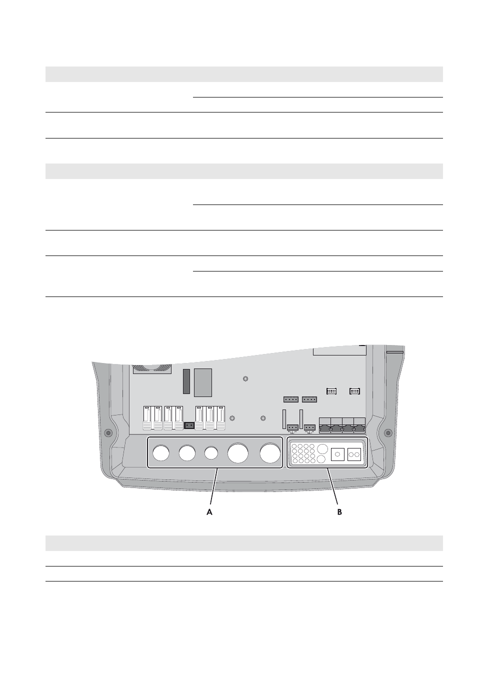
7.7 Sealing and Closing the Sunny Island
Figure 19: Position of the cable glands and the cable feed-through plate
Test point
Test criterion
OK
Electricity supply to communication
products
The plug-in power supply units are plugged in.
□
The communication products are connected to an electricity supply.
□
Termination of the communication buses
The communication buses are connected to the first and last device
in the bus.
□
Test point
Test criterion
OK
System devices
All system devices are correctly connected (see the manuals for the
devices).
□
Ensure by measuring that all system devices are connected with the
same ground potential.
□
Connection AC1 in the off-grid system
The stand-alone grid or the Multicluster Box is connected to the
AC1 Loads/SunnyBoys terminals.
□
Connection AC2 in the off-grid system
The generator is connected to connection AC2 Gen/Grid.
□
The neutral conductor is connected to the terminal AC2 Gen/
Grid N.
□
Position
Designation
A
Cable glands
B
Cable feed-through plate