SMA SI 3.0-11 Installation User Manual
Page 48
7 Electrical Connection
SMA Solar Technology AG
48
SI30M-44M-60H-80H-IA-en-30
Installation Manual
7.4.17 Connecting the Control Cable for the Use of Excess Energy in an
Off-Grid System
If the battery can no longer take up excess energy in an off-grid system, the power output of the AC sources
in the stand-alone grid is limited by the Sunny Island. This means that the excess energy is not used. The Sunny Island
allows for the use of excess energy by means of a multifunction relay.
During the constant voltage phase, a multifunction relay is activated and thus controls additional loads that can put any
excess energy to good use. As a result of the utilization of excess energy, the Sunny Island has to limit the power output
of the AC sources in the stand-alone grid to a lesser extent.
Requirements:
☐ The technical requirements of the multifunction relay must be met (see Section 10 "Technical Data", page 94).
Cable requirements:
☐ Copper wire
☐ Conductor cross-section: 0.2 mm² to 2.5 mm²
Procedure:
2. Enter the function of the multifunction relay used in the configuration table (see Section 8.1.5 "Setting the Functions
of the Multifunction Relays", page 66). Note the ExtPwrDer value.
3. After performing basic system configuration, adjust the multifunction relay (see Section 8.1.5, page 66) and function
Example: Utilization of excess energy
The energy source of an off-grid system is PV energy. On days with high solar irradiation and low power consumption,
the battery cannot take up all of the PV energy during the constant voltage phase. In order to utilize the excess energy,
the Sunny Island activates the control of a pump that pumps water into a container for subsequent use.
1.
:$51,1*
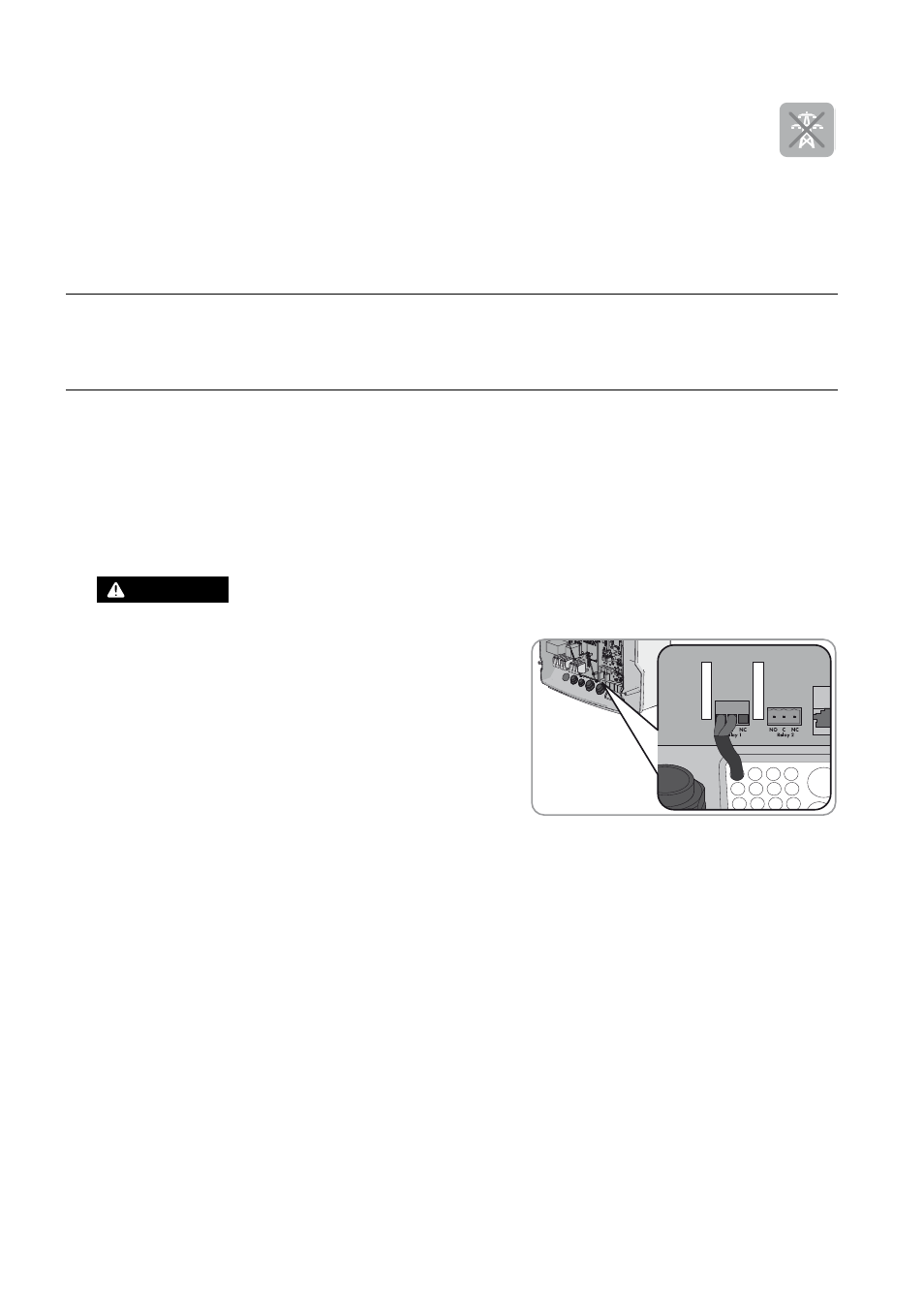
Danger to life from electric shock due to incorrect insulation
• On the Sunny Island, connect the control cable for the
utilization of excess energy to the multifunction relay (see