SMA SI 3.0-11 Installation User Manual
Page 51
SMA Solar Technology AG
7 Electrical Connection
Installation Manual
SI30M-44M-60H-80H-IA-en-30
51
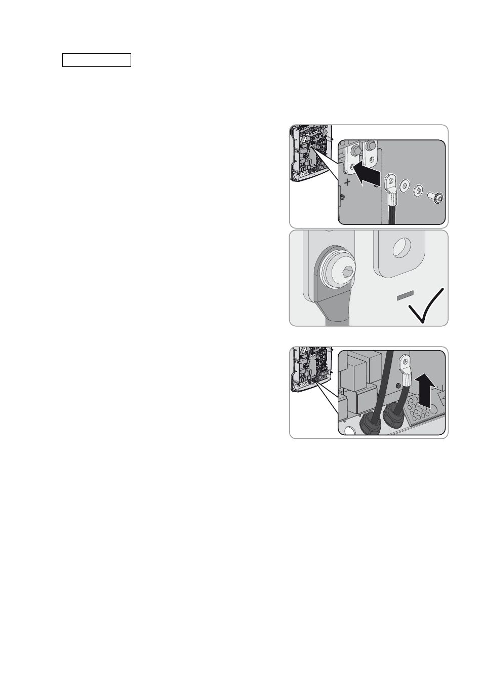
8. Strip the insulation off the DC– cable and mount a terminal lug.
9. Lead the DC– cable through the DC– cable gland into the
Sunny Island.
10. Route the DC– cable on the side of the protective cover marked with a – symbol.
7.
/05*$&
Damage to Sunny Island inverter due to reverse polarity or incorrect terminal lug selection
If the DC cables are swapped, high currents will flow after the load-break switch has closed and these can damage
the Sunny Island.
• Route the DC+ cable on the side of the protective cover marked with a + symbol.
• Use an Allen key (AF 5) to fasten the DC+ cable to the
DC+ connection with an M8x20 screw (torque: 12 Nm).
Be sure to adhere to the following screw assembly: screw
head | spring washer | fender washer | terminal lug |
DC connection.
☑ The entire contact surface of the fender washer is in
contact with the terminal lug.