SMA SI 3.0-11 Installation User Manual
Page 28
7 Electrical Connection
SMA Solar Technology AG
28
SI30M-44M-60H-80H-IA-en-30
Installation Manual
7.4.2 Connecting the Utility Grid in the System for Increased
Self-Consumption
Requirements:
☐ The system is not a battery backup system
☐ For connection of the Sunny Island inverter to the utility grid, there must be a circuit breaker and a type A
residual-current device on the distribution board (for circuitry overview, see the Quick Reference Guide
"SMA Flexible Storage System").
Procedure:
1. On the Sunny Island, connect the power cable to the terminals
AC2 Gen/Grid: Ensure that the cable is correctly connected (see
Section 7.5.2 "Connecting the AC Power Cable", page 52).
• Connect the line conductor to AC2 Gen/Grid L.
• Connect the neutral conductor to AC2 Gen/Grid N
TT
.
• Connect the grounding conductor to AC2 Gen/Grid PE.
2. Connect an additional grounding conductor to the AC1 Loads/SunnyBoys PE terminal if the power cable
conductor cross-section is smaller than 10 mm² (see Section 7.5.3 "Connecting the Grounding Conductor",
4.
/05*$&
Damage to Sunny Island inverter due to reverse polarity or incorrect terminal lug selection
If the DC cables are swapped, high currents will flow after the load-break switch has closed and these can damage
the Sunny Island.
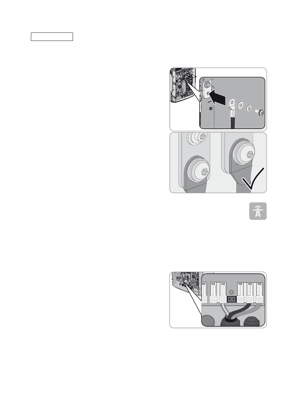
• Fasten the DC power cables to the DC connection with
M8x20 screws, ensuring correct polarity (torque: 12 Nm). In
doing so, ensure that the cable is connected correctly (see
Section 7.5.1 "Connecting the DC Power Cable", page 50)
and adhere to the following screw assembly: screw head |
spring washer | fender washer | terminal lug | DC
connection.
☑ The contact surfaces of the fender washers have full
contact with the terminal lugs.